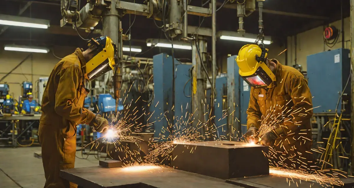
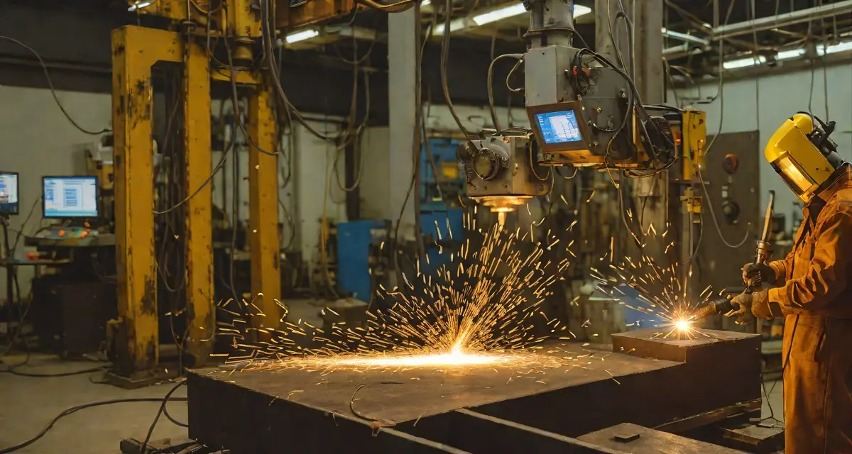
When fabricating thick-walled pressure vessels, structural columns, or subsea pipelines, a single weld joint can require ten, twenty, or even fifty individual passes. Each pass deposits a new layer of filler metal on top of the previous one, and each layer must cool to the correct temperature before the next begins. Get the sequence wrong and the result is hydrogen cracking, lack of fusion, or residual stress that shortens the service life of the entire assembly. Multi-pass welding monitoring with thermal cameras provides the continuous, objective data needed to control this complex process from root pass to cap pass.
In this article we examine why multi-pass welds are uniquely difficult to control, how infrared thermography addresses the core challenges, and what a practical monitoring architecture looks like on a modern fabrication line.
Why Multi-Pass Welds Demand Continuous Monitoring
Most inline weld inspection conversations focus on single-pass or two-pass joints common in automotive body-in-white production. Multi-pass welding is a fundamentally different challenge for three reasons:
1. Cumulative Heat Build-Up
Each pass adds thermal energy to the joint. If the operator or robot proceeds too quickly, the base metal and previous passes overheat. The heat-affected zone (HAZ) grows beyond specification, grain coarsening reduces toughness, and in austenitic stainless steels, sensitization and intergranular corrosion become real risks. Conversely, if the workpiece cools too far between passes, the risk of hydrogen-induced cracking in high-strength low-alloy steels rises sharply.
2. Interpass Temperature Windows Are Narrow
Welding procedure specifications (WPS) define both a minimum preheat temperature and a maximum interpass temperature for every qualified procedure. ISO 13916 specifies exactly where and how interpass temperature measurements should be taken. In practice, many shops still rely on a single thermocouple or a contact pyrometer held against the plate between passes. This gives one data point in one location at one moment, while the actual temperature field across a multi-pass joint is highly non-uniform.
3. Defects Hide Between Layers
A lack-of-fusion defect between pass three and pass four will be buried under six more layers of weld metal before the joint reaches NDT. By that point, the defect is invisible to visual inspection and difficult to detect even with radiography if its orientation is unfavorable. Real-time monitoring during each pass is the only way to flag anomalies before they are entombed.
How Thermal Cameras Solve the Multi-Pass Problem
Industrial infrared cameras operating in the mid-wave infrared (MWIR, 3 to 5 micrometers) or long-wave infrared (LWIR, 8 to 14 micrometers) band can image the entire weld zone at frame rates of 50 Hz or higher. For multi-pass welding, this delivers four critical capabilities.
Full-Field Interpass Temperature Mapping
Rather than measuring temperature at a single point, a thermal camera captures the temperature distribution across the entire joint preparation. The monitoring system can present a color-coded thermal map that shows whether any region of the groove is above the maximum interpass temperature or below the minimum preheat threshold. This eliminates the guesswork that leads to either premature starts (risking hot cracking and excessive distortion) or unnecessary waiting (reducing productivity).
As we covered in our guide on welding preheat and interpass temperature monitoring, compliance with interpass requirements is not optional. It is a documented WPS parameter that auditors verify. A thermal camera system produces time-stamped, spatially resolved evidence that every pass started within specification.
Layer-by-Layer Thermal Signature Tracking
Each weld pass produces a characteristic thermal profile: a peak temperature during the arc, a cooling curve after the arc passes, and a steady-state temperature when equilibrium is reached. In a well-controlled multi-pass weld, these signatures are consistent from pass to pass, with predictable variations due to increasing joint volume and changing heat sink geometry.
When something goes wrong, the thermal signature deviates. A sudden temperature spike in the trailing region may indicate a lack of fusion with the sidewall. An abnormally slow cooling rate can signal excessive heat input that will produce an oversized HAZ. A localized cold spot within the weld bead suggests incomplete filling or porosity. AI-based monitoring systems like HeatCore learn the expected thermal envelope for each pass number and flag deviations in real time, giving the operator or robot controller the chance to correct before the next pass buries the evidence.
Cooling Rate and T8/5 Calculation
The cooling time from 800 degrees Celsius to 500 degrees Celsius (T8/5) is the single most important metallurgical parameter in carbon and low-alloy steel welding. It governs the final microstructure of the HAZ: too fast and you get hard, brittle martensite; too slow and grain growth reduces impact toughness. We explored this relationship in depth in our article on heat input, cooling rate, and microstructure.
In multi-pass welding, T8/5 varies from pass to pass because the thermal boundary conditions change. The root pass cools against the full thickness of cold base metal. Fill passes cool against a combination of previously deposited weld metal (which may still be warm) and the groove sidewalls. Cap passes cool with one surface exposed to ambient air. A thermal camera system calculates T8/5 for every pass, providing a complete metallurgical record of the joint — see a layer-by-layer cooling-time analysis captured live.
Distortion Monitoring Across the Build-Up
As weld metal is deposited pass by pass, asymmetric heat input drives angular distortion, longitudinal shrinkage, and transverse bowing. The thermal camera captures the temperature gradients that drive these distortions in real time. When integrated with process models, this data enables predictive correction of welding sequence and heat input. For more on this topic, see our dedicated article on weld distortion monitoring.
Multi-Pass Monitoring Architecture
A practical multi-pass weld monitoring system integrates thermal imaging with the welding equipment, the quality management system, and the production schedule. Here is the architecture used in modern heavy fabrication.
Sensor Placement
For groove welds on plate or pipe, the thermal camera is typically mounted on the welding manipulator or column-and-boom, positioned to view the weld pool and a trailing zone of approximately 100 to 200 millimeters. In manual welding, a fixed camera with a wider field of view covers the entire joint preparation. The camera must be protected from arc radiation (using appropriate spectral filtering) and from spatter (using an air purge or protective window).
Data Flow
The camera streams thermal frames to an edge computing unit that runs the monitoring algorithms. Key outputs include:
- Interpass temperature: Go/no-go signal before each pass starts
- Peak temperature per pass: Compared against WPS limits
- T8/5 per pass: Logged for metallurgical traceability
- Anomaly flags: Lack of fusion, porosity, undercut, or excessive penetration indicators
- Cumulative heat map: Total thermal exposure of the joint over all passes
These outputs are pushed to the quality management system as structured digital records, replacing manual datasheets. Systems like the HeatCore QMS workflow can automatically attach thermal data to the weld joint record, linking it to the applicable WPS, the welder or operator qualification, and the material certificates.
Integration with Welding Power Sources
Modern power sources communicate over digital bus protocols. The monitoring system can correlate thermal data with arc voltage, current, wire feed speed, and travel speed on a frame-by-frame basis. This correlation is essential for root cause analysis: when a thermal anomaly appears, the system can immediately determine whether it was caused by a process parameter deviation (such as a wire feed interruption) or a joint preparation issue (such as a gap variation).
Standards and Compliance Requirements
Multi-pass welding on critical components is governed by a rigorous standards framework.
ISO 3834-2:2021 (comprehensive quality requirements for fusion welding) requires that production welding be monitored and that records demonstrate compliance with the qualified WPS. For multi-pass welds, this means documenting interpass temperature compliance for every pass on every joint, a requirement that is practically impossible to satisfy with manual spot checks but straightforward with continuous thermal monitoring.
The American Welding Society structural welding codes (D1.1 for steel, D1.6 for stainless steel) specify maximum interpass temperatures and minimum preheat requirements that vary by material group and thickness. AWS D1.1 Table 4.4, for example, defines preheat and interpass requirements based on steel category, thickness, and hydrogen level of the consumable. Thermal camera monitoring provides the audit-ready evidence that these requirements were met.
ASME Boiler and Pressure Vessel Code Section IX defines welding procedure qualification, while the construction codes (Section I for power boilers, Section VIII for pressure vessels) specify the production monitoring requirements. For multi-pass welds on pressure-retaining components, continuous thermal monitoring is increasingly recognized as best practice by authorized inspection agencies.
Practical Benefits for Heavy Fabricators
Reduced Wait Time Between Passes
The most immediate productivity benefit is eliminating unnecessary cooling time. When an operator relies on a contact pyrometer, they often add a safety margin by waiting longer than necessary. A thermal camera shows the actual temperature field in real time. As soon as the hottest point in the groove drops below the maximum interpass temperature, the system gives a green light. On thick-walled joints requiring 20 or more passes, saving even two minutes per pass adds up to more than 40 minutes per joint.
Fewer Repairs and Lower Rework Costs
Multi-pass weld repairs are expensive. Gouging out a buried defect, re-preparing the groove, and re-welding can cost ten to twenty times more than the original weld. When thermal monitoring flags an anomaly on pass four, the correction involves grinding back one or two passes, not excavating through ten layers of weld metal. As discussed in our analysis of weld defect costs, the economics of early detection are compelling.
Complete Digital Traceability
Every pass is documented with time-stamped thermal data, process parameters, and operator identification. This creates a digital weld quality record that satisfies the most demanding audit requirements, from nuclear (ASME NCA) to offshore (NORSOK M-601) to structural (EN 1090 EXC3 and EXC4).
Data-Driven Procedure Optimization
Over time, the accumulated thermal data from hundreds of multi-pass joints reveals optimization opportunities. Perhaps the fill passes on a particular joint design consistently run cooler than the interpass maximum, indicating that travel speed could be increased. Or perhaps a specific pass sequence produces lower distortion than the sequence specified in the original WPS. This data enables evidence-based procedure refinement that improves both quality and productivity.
Implementation Considerations
Camera Selection
For multi-pass monitoring, mid-wave infrared (MWIR) cameras with InSb detectors offer the best combination of temperature range (typically 300 degrees Celsius to 1500 degrees Celsius) and spatial resolution. The camera should have a frame rate of at least 50 Hz and a detector resolution of 640 by 512 pixels or higher to provide sufficient detail across the weld zone. Compare thermal camera and software options to match the detector and frame rate to your joint mix.
Environmental Protection
Heavy fabrication environments are harsh. The camera needs an IP65 or IP67-rated housing with an air purge system to keep the optical window clear of fume and spatter. The air purge also prevents hot particles from settling on the window and creating false thermal readings.
Calibration and Emissivity
Weld metal emissivity changes with surface condition (oxidation state, roughness, and temperature). Accurate temperature measurement requires either a known emissivity model or a multi-wavelength approach. For interpass temperature monitoring, where the surface has cooled and oxidized to a consistent state, single-band cameras with a calibrated emissivity value provide sufficient accuracy for WPS compliance. For peak temperature measurements during the arc, ratio pyrometry or MWIR cameras with appropriate spectral filters are preferred.
Getting Started with Multi-Pass Weld Monitoring
The transition from manual interpass checks to continuous thermal monitoring does not require replacing your entire quality system overnight. A practical starting point is:
- Identify your highest-risk joints: Start with the joints that have the highest repair rate or the most stringent interpass requirements.
- Install a single camera system: Mount one thermal camera on a representative welding station and run it in monitoring (not control) mode for two to four weeks.
- Collect baseline data: Use the thermal data to establish the normal operating envelope for your standard procedures.
- Set alert thresholds: Configure the system to flag passes that deviate from the baseline by more than a defined tolerance.
- Expand to production use: Once validated, extend to additional stations and integrate with your quality management system.
Ready to Monitor Every Pass?
HeatCore provides real-time thermal monitoring for multi-pass welding, with automated interpass temperature verification, layer-by-layer defect detection, and complete digital traceability. See how it works on your joints.
Book a DemoConclusion
Multi-pass welding is one of the most demanding processes in industrial fabrication. The cumulative thermal effects, the narrow interpass temperature windows, and the risk of buried defects make it uniquely suited to continuous thermal monitoring. By replacing manual spot checks with full-field infrared imaging, fabricators gain precise interpass temperature control, real-time anomaly detection, complete metallurgical traceability, and the data needed to optimize their procedures over time.
The technology is proven, the standards increasingly expect it, and the economics are clear. For any fabricator running multi-pass welds on critical components, thermal monitoring is no longer a nice-to-have. It is the standard of care.
Therness solution: Welding monitoring system — Every weld inspected in the cycle, with defect flags and the ISO 3834 / ISO 17635 evidence kept per weld.