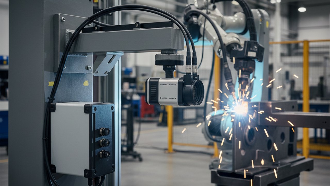
Writing the specification for a weld camera is harder than it looks. The arc is one of the most hostile optical environments in manufacturing: intense broadband emission from 200 nm to 1400 nm, spattering droplets, fumes, and rapid motion of the weld pool. A camera that delivers sharp footage in a demo booth may produce nothing useful 200 mm from a live arc welding process if it was not designed for the task.
This is a specification and commissioning guide. It covers the numbers you put in a requirement — resolution, frame rate, dynamic range, IP rating, working distance, output interface — then the mounting geometry, air purge, PLC and robot integration, and the acceptance tests that decide whether the install still works in month six. The same logic applies whether you are equipping a single manual bay or a fleet of robotic welding cells.
Start with the hub, not with this page. This guide is a companion to the main weld monitoring camera hub: that page explains what a weld monitoring camera is, which camera families exist, what each one is for, and how the thermal and high-speed models compare side by side. Come back here once you know the modality and need to turn that choice into a purchasable specification.
Key Takeaways
- Match the camera to the arc, not the demo: insist on arc glare rejection data measured at your actual arc power and working distance before any specification is accepted.
- Choose modality by question: visual CCD/CMOS for weld pool geometry, spatter, and arc behaviour; LWIR thermal for temperature fields, preheat/interpass compliance, and heat-affected-zone extent.
- Size resolution and frame rate to the feature: roughly 0.35 mm per pixel at 200 mm covers pool width; 25 to 60 fps suits heat distribution while 240 fps or higher captures pool dynamics.
- Specify the housing for the floor: IP54 minimum (IP67 for wash-down), continuous-duty ambient temperature, air purge, and a tool-free quick-change optical window.
- Integrate at the right level: Level 2 event-triggered capture is the minimum for ISO 3834 traceability; Level 3 real-time feedback enables closed-loop adaptive welding.
- The dominant in-service failure is window contamination, not electronics; design the optical path and air purge to keep the window clean and serviceable in under five minutes.
- Commission with quantitative acceptance criteria and re-verify after every maintenance event so image quality is proven, not assumed.
Table of Contents
- Visual vs Thermal: Choosing Your Imaging Modality
- Key Specifications to Evaluate
- Mounting, Air Purge, and Housing Setup
- Integration with PLCs, Robots, and MES
- Common Setup Failure Modes and Fixes
- Step-by-Step Commissioning and Validation
- FAQ
Visual vs Thermal: Choosing Your Imaging Modality
Weld cameras divide into two broad families with different strengths, and the first decision in any specification is which question you are trying to answer.
Visual (CCD/CMOS) cameras capture light in the visible and near-infrared spectrum using a silicon image sensor. They provide intuitive, video-like footage that operators and engineers can interpret immediately. The challenge is the arc: an unfiltered sensor pointed at a gas metal arc welding (GMAW) or GTAW arc is instantly saturated. Solving this requires one of three strategies, often in combination: very fast electronic shutters (1/100,000 s or faster), bandpass filters that pass a narrow wavelength away from peak arc emission, or specialised illumination that makes the weld pool visible at a wavelength where the arc is comparatively dim. The physics behind each approach, and why a single measure is rarely enough, is treated in depth in the guide to arc glare and laser-safe illumination.
Thermal cameras detect long-wave infrared (LWIR) radiation in the 8 to 14 µm range. At these wavelengths the arc does not saturate the detector the way it does in the visible spectrum, because most arc radiation is concentrated in the UV, visible, and near-infrared bands. Thermal cameras show the heat distribution across the weld zone in real time, measuring interpass temperature, HAZ extent, and cooling rates without contact — the role filled by a cylindrical unit such as the HeatCam IR-C at a fixed weld station, or the compact HeatCam IR-S for embedded and space-constrained mounts. The trade-off is spatial resolution: LWIR detector arrays are physically larger and more expensive per pixel than visible-light sensors, so thermal cameras typically resolve fewer pixels per degree of field of view.
A useful way to frame the choice is by the measurand. Visual cameras measure geometry and dynamics; thermal cameras measure temperature. They are complementary, not competing, and the decision criteria are laid out side by side in the welding camera vs thermal camera comparison.
Practical rule: Use a visual camera when you need to observe weld pool geometry, spatter, and arc behaviour. Use a thermal camera when you need to measure temperature fields, monitor preheat and interpass compliance, or track the heat-affected zone. Many production setups deploy both modalities on the same joint and fuse the streams downstream.
For high-deposition processes such as wire-arc additive manufacturing, the case for dual-modality monitoring is even stronger, because both bead geometry and thermal history drive part quality — a workflow described in the WAAM additive manufacturing monitoring guide.
Key Specifications to Evaluate
Before sending a request for quotation, define your requirements against the dimensions below. The aim is to convert vague marketing language into measurable acceptance criteria a supplier can be held to.
Resolution and Frame Rate
For weld pool observation, the target feature is typically 0.5 to 5 mm across. At a 200 mm working distance, a 640 × 480 pixel sensor with a 25 mm lens subtends roughly 0.35 mm per pixel — sufficient for pool width and toe geometry, but marginal for early-stage porosity tracking. As a rule of thumb, you want at least three to five pixels across the smallest feature you intend to measure. High-speed cameras (240 to 1000 fps) capture pool dynamics during short-circuit GMAW or pulsed GTAW; standard 25 to 60 fps is adequate for heat distribution and pass-to-pass tracking. The trade-off is data volume: a 1000 fps stream at full resolution can saturate a GigE link, so high-speed work often uses a region of interest or on-camera triggering. For weld-pool dynamics specifically, the 480 fps weld pool camera guide explains why temporal resolution often matters more than pixel count. For that high-speed regime, the PoolDrop weld-pool camera captures droplet transfer at 480 fps.
Dynamic Range and Arc Glare Rejection
A camera rated for “high dynamic range” in a machine-vision context (10 to 12 bit) may still be inadequate near a live arc. Evaluate the vendor’s data at the actual arc power you intend to monitor, and reject specifications that quote dynamic range from a bench test without reporting arc-distance conditions. The relevant principles of sensor characterisation — quantum efficiency, dynamic range, signal-to-noise ratio — are standardised in the EMVA 1288 specification, which gives you a vocabulary to compare datasheets on equal terms.
Illumination-based approaches place a narrowband light source at a wavelength selected to dominate arc emission at the sensor, making the weld pool visible against a relatively dim background. This requires the illumination and filter to be matched precisely to the camera’s spectral sensitivity and is sensitive to contamination of the illumination optic. Any safety-rated illumination must comply with the photobiological framework set out in IEC 62471, and laser-based sources additionally fall under IEC 60825-1.
IP Rating and Temperature Range
The camera housing must be rated to IEC 60529 IP54 or higher for standard shop environments (spatter, grinding dust, coolant mist). Robotic cells with wash-down cycles may need IP67. Operating temperature range matters particularly for thermal cameras — LWIR detectors drift with ambient temperature if the camera lacks internal compensation. Confirm the rated ambient temperature applies at continuous duty, not just a peak figure, and that the IP rating covers the complete assembly including the optical window seal.
Working Distance and Depth of Field
A camera mounted 300 mm from the arc requires a different lens than one mounted 1000 mm away. Define your minimum and maximum working distances and the field of view you need at each extreme, then calculate the focal length. Verify that depth of field at maximum working distance still covers the full width of the joint, including any out-of-position or convex profiles where the pool surface is not flat to the lens axis.
Output Interface
Modern weld cameras output over GigE Vision (Gigabit Ethernet with the GigE Vision protocol), Camera Link, USB3 Vision, or proprietary industrial protocols. GigE Vision is the most integration-friendly: it runs over standard Cat 5e/6 cable up to 100 m, requires no frame-grabber card, and is supported by most vision software and PLC OPC-UA bridges. Camera Link offers higher deterministic bandwidth for very high frame rates but needs a frame grabber and short cable runs.
| Parameter | Minimum Requirement | Notes |
|---|---|---|
| Imaging modality | Visual or thermal matched to application | Dual modality for full coverage |
| Resolution | 640 × 480 px (visual); 320 × 240 px (thermal) | At least 3–5 px across smallest feature |
| Frame rate | 25 fps standard; 240 fps for pulsed/short-circuit | Mind GigE bandwidth at full resolution |
| Dynamic range | ≥ 10 bit; 12 bit for quantitative geometry | Quoted with arc-distance conditions |
| Arc glare rejection | Demonstrated at target arc power and distance | Request arc-condition test data |
| Housing IP rating | IP54 minimum; IP67 for wash-down cells | Rating must cover window seal |
| Ambient operating temp | 0–50 °C minimum, continuous duty | Wider if near furnace or curing oven |
| Output interface | GigE Vision preferred | Camera Link for legacy / very high fps |
| Air purge | Required for any open-arc process | Check fitting vs house air pressure |
| PLC integration | Digital I/O trigger + GigE Vision | OPC-UA bridge for Level 3 |
A structured walkthrough of how to weigh these parameters against a budget and an application is provided in the 2026 welding camera buyer’s guide — or compare the full Therness camera lineup directly.
Mounting, Air Purge, and Housing Setup
The most common failure mode for weld cameras in production is not electronics failure — it is contamination of the optic window by spatter or fume. Design the mounting so the window can be serviced in under five minutes without tools.
Optical and mechanical setup decides whether a well-specified camera actually performs on the floor. The key mounting decisions are as follows.
Fixed vs Robot-Mounted
A fixed camera on a floor stand or weld fixture gives a stable field of view and simplifies integration, at the cost of needing the joint to come to the camera. A robot-mounted camera moves with the torch, maintaining a constant working distance and viewing angle across the weld path, at the cost of cabling complexity and the need to manage cable runs on a multi-axis arm. For torch-mounted installations, cable strain relief, connector orientation, and the interaction with the robot’s wrist envelope are critical, and they are covered in the camera for robotic welding cells integration guide.
Air Purge
An air-purge fitting on the camera housing directs filtered shop air across the optic window to deflect spatter and fume. Critical parameters:
- Flow rate: 5 to 15 L/min is typically sufficient. Below 5 L/min the airflow cannot deflect spatter; above roughly 25 L/min, turbulence can degrade thermal measurements if a thermal camera is co-located.
- Air purity: ISO 8573-1 Class 3 or better, with low oil and particulate content. Contaminated purge air deposits hydrocarbon films on the window faster than welding fume alone, so a coalescing filter on the supply line is essential.
- Purge direction: Across the window face at a shallow angle, not impinging directly on it. Direct impingement can trap spatter against the glass rather than deflecting it.
Thermal Management and Window Choice
Electronics operating continuously near a welding cell accumulate heat. Verify the camera’s rated ambient operating temperature and, if necessary, specify active cooling or a thermally isolated housing. Use a borosilicate optical window with an anti-reflection coating; avoid polycarbonate, which yellows and hazes under arc UV within weeks. Specify a quick-change window retention scheme so a fogged window is a routine consumable swap, not a teardown. General machine-vision integration practice from the Association for Advancing Automation reinforces that serviceability, not peak specification, is what keeps a vision system running across shifts.
Integration with PLCs, Robots, and MES
A weld camera that produces images without integrating into the process control loop has limited value. Three integration levels are common in production environments, and each carries a different cost and compliance benefit.
Level 1: Live Video and Manual Review
The camera streams to a monitor at the welding station or a supervisor workstation. Operators watch the feed and flag anomalies manually. Setup is fast and the hardware is minimal, but this level provides no automated rejection and no traceable log — it is a viewing aid, not a quality record.
Level 2: Event-Triggered Image Capture
The PLC sends a digital trigger to the camera at defined weld events — arc-on, pass complete, weld-end. The camera saves a snapshot or short clip tagged with the job number and timestamp, indexed for post-weld review. This is the minimum level required for ISO 3834 weld traceability evidence under the Part 2 and Part 3 quality requirements, and it integrates cleanly with welding NCR management workflows when an anomaly is flagged.
Level 3: Real-Time Parameter Feedback
The camera output is processed by a vision system or embedded inference engine that extracts metrics — pool width, bead geometry deviation, temperature isotherm width — and returns these as process signals to the PLC or robot controller. The controller can adjust wire feed rate, travel speed, or pause and generate a non-conformance record automatically. This is the architecture needed for closed-loop adaptive welding, and it is where an AI layer such as HeatCore AI turns raw imagery into actionable process signals. A complementary overview of the full sensing-to-control chain is given in the weld monitoring system reference. See the AI monitoring system in action.
For compliance with structural welding standards, documented evidence of monitoring is required for the higher weld classes. International quality requirements for fusion welding are defined by the International Organization for Standardization in the ISO 3834 series, while professional guidance on in-process monitoring practice is published by TWI and the International Institute of Welding. Level 2 and Level 3 integration generate the required evidence automatically; Level 1 does not.
| Integration level | What it produces | Typical use | Traceability |
|---|---|---|---|
| Level 1 — live video | Real-time feed, no record | Manual supervision, training | None |
| Level 2 — event capture | Job-tagged timestamped images | Post-weld review, audit evidence | ISO 3834 CL1/CL2 |
| Level 3 — real-time feedback | Process metrics to controller | Closed-loop adaptive welding | Full, with control log |
Common Setup Failure Modes and Fixes
The failure modes below account for the majority of “the camera doesn’t work” complaints in production weld monitoring installations. Each has a defined root cause and a repeatable corrective action — most are setup or maintenance issues, not hardware defects.
| Failure Mode | Symptom | Root Cause | Corrective Action |
|---|---|---|---|
| Window fogging | Image darkens over a shift; worse at weld start | Spatter or fume deposition on the optic window | Increase or redirect air purge; add a heat shield at the window; schedule cleaning every 4–8 h; fit a quick-change window |
| Arc saturation | Pool centre overexposed; bright halo | Glare rejection under-specified for actual arc power | Verify filter/illumination spec at the real arc; add or correct bandpass filtering; reduce gain or exposure |
| Illumination loss | Image dims with no visible window fogging | Illuminator optic fouling or driver degradation | Clean the illuminator optic; measure drive current; replace the source module if output is below 70% of rated |
| Image position drift | Pool location drifts in frame over a shift | Mount vibration or thermal expansion of bracket | Re-torque fasteners; add vibration-isolating washers; place a fiducial in the field of view for drift detection |
| Dropped frames / no capture | Missing snapshots at trigger events | GigE bandwidth saturation or trigger wiring fault | Reduce ROI or frame rate; verify jumbo frames and link speed; check PLC trigger continuity and debounce |
| Thermal reading drift | Temperature values trend with ambient | Uncompensated LWIR detector or hot housing | Enable internal compensation; isolate or cool the housing; recalibrate against a reference per ISO 13916 |
Setup tip: Before blaming the camera, log the air-purge pressure, the measured arc current, and the camera gain at the moment a complaint occurs. The majority of “camera failures” reconcile to one of these three variables drifting out of the commissioned window.
Step-by-Step Commissioning and Validation
A weld camera should be commissioned against quantitative acceptance criteria, not declared working because the picture looks reasonable. The procedure below produces a documented record suitable for audit, in line with traceability expectations under structural welding codes such as AWS D1.1.
Step 1 — Static Reference and Focus
With the camera at the nominal working distance and any illumination active, image a static reference surface (a marked coupon or grid). Confirm focus across the full field of view and verify the measured pixel scale matches the design calculation (for example, 0.35 mm per pixel at 200 mm). Record the lens, working distance, and pixel scale in the commissioning sheet.
Step 2 — Signal-to-Noise Baseline (Arc Off)
Capture 50 frames of the static reference. Compute the mean and standard deviation of grey values in a 50 × 50 pixel region; SNR is mean divided by standard deviation. A low baseline SNR points to excessive gain, sensor noise, or insufficient illumination for the working distance — fix it now, because arc-on conditions only make it worse.
Step 3 — Arc-On Saturation and Contrast
Run a standard weld coupon at your nominal parameters and capture at least 100 frames during the arc. For each frame compute the fraction of pixels in the pool region at grey value 250/255 or above; target fewer than 5% saturated pixels. Then compute the contrast between the pool and adjacent solid metal; if the pool boundary is not clearly resolvable in more than 90% of frames, revisit glare rejection, illumination, or exposure before accepting the system.
Step 4 — Trigger and Integration Verification
Exercise the PLC trigger at each defined weld event and confirm that every triggered image is saved with the correct job number and timestamp. For a Level 3 installation, verify that the extracted metric (pool width, isotherm width) is delivered to the controller within the required cycle time and that an induced fault produces the expected control response or record. Document the end-to-end latency.
Step 5 — Document and Re-Validate
Record all measured values with date and operator in the weld quality system, creating the audit trail that supports your monitoring evidence. Repeat Steps 1 to 3 after every window cleaning, after any camera or illuminator replacement, and after any change to mounting geometry. Quantitative acceptance criteria captured at commissioning and re-verified after maintenance — rather than assumed from a bench test — are what keep a monitoring claim defensible. For installations that need formal help defining these criteria against a specific process and code, welding process consulting can structure the qualification, and additional templates are available in the resources library.
FAQ
What specifications matter most when selecting a weld monitoring camera?
Prioritise arc glare rejection demonstrated at your actual arc power and working distance, then resolution and frame rate matched to the feature size you need to resolve, dynamic range of at least 10 bit, an IP54 or higher housing, and a GigE Vision output for integration. A camera that looks sharp in a demo can produce nothing usable 200 mm from a live arc if it was not designed for the spectral conditions.
Should I use a visual or a thermal weld monitoring camera?
Use a visual CCD/CMOS camera when you need to observe weld pool geometry, spatter, and arc behaviour in the visible spectrum. Use an LWIR thermal camera when you need to measure temperature fields, preheat and interpass compliance, or heat-affected-zone extent. Many production cells deploy both modalities on the same joint because they answer different questions.
What resolution and frame rate does a weld monitoring camera need?
For weld pool geometry the target feature is typically 0.5 to 5 mm across, so a 640 × 480 pixel visual sensor at 200 mm working distance with a 25 mm lens gives roughly 0.35 mm per pixel, which is adequate for pool width and toe geometry. Use 25 to 60 fps for heat distribution and pass-to-pass tracking, and 240 fps or higher to capture pool dynamics during short-circuit or pulsed transfer.
How do I integrate a weld monitoring camera with a PLC or robot?
Three levels are common. Level 1 streams live video for manual review. Level 2 uses a PLC digital trigger to capture timestamped, job-tagged snapshots at arc-on, pass-complete, and weld-end events. Level 3 processes the image stream in real time and returns metrics such as pool width or isotherm width to the controller for closed-loop parameter adjustment. GigE Vision plus digital I/O, with an OPC-UA bridge for Level 3, covers most cells.
What IP rating and operating temperature does a weld camera housing need?
IP54 per IEC 60529 is the minimum for standard shop environments with spatter and grinding dust, and IP67 is required for wash-down cells. Confirm a continuous-duty ambient operating temperature, typically 0 to 50 degrees Celsius, and verify the rating applies to the complete assembly including the optical window seal, not only the electronics housing.
Why do weld monitoring cameras fail in production?
The most common in-service failure is contamination of the optic window by spatter or fume, not electronics failure. Other frequent issues are arc saturation when glare rejection is under-specified, illumination intensity loss as the illuminator optic fouls, image drift from mount vibration, and trigger or network faults that interrupt capture. Most are preventable with air purge, a quick-change window, and a documented commissioning procedure.
What air purge flow rate does a weld camera window need?
A flow of 5 to 15 L/min of clean, dry shop air across the window face is typically sufficient to deflect spatter and fume. Below 5 L/min the airflow cannot deflect spatter; above roughly 25 L/min turbulence can degrade co-located thermal measurements. Direct the purge across the window at a shallow angle rather than impinging on it, and use ISO 8573-1 Class 3 or better air to avoid depositing oil films.
Does a weld monitoring camera provide ISO 3834 traceability evidence?
Yes, when integrated at Level 2 or Level 3. Event-triggered capture that saves job-tagged, timestamped images creates the documented monitoring evidence required for weld classes CL1 and CL2 under ISO 3834-2 and structural codes such as EN 15085. Level 1 manual viewing alone does not generate a traceable record, so it does not satisfy the documented-evidence requirement.
Talk to a Weld Camera Specialist
Describe your welding process, materials, working distance, and integration requirements. Our applications engineers will recommend the right camera configuration and integration path for your cell, with arc-condition test data before any hardware commitment.
Contact the applications teamTherness solution: Welding camera — Thermal and high-speed imaging that watches the arc, the pool and the cooling seam while the weld is made.
Frequently Asked Questions
What specifications matter most when selecting a weld monitoring camera?
Prioritise arc glare rejection demonstrated at your actual arc power and working distance, then resolution and frame rate matched to the feature size you need to resolve, dynamic range of at least 10 bit, an IP54 or higher housing, and a GigE Vision output for integration. A camera that looks sharp in a demo can produce nothing usable 200 mm from a live arc if it was not designed for the spectral conditions.
Should I use a visual or a thermal weld monitoring camera?
Use a visual CCD/CMOS camera when you need to observe weld pool geometry, spatter, and arc behaviour in the visible spectrum. Use an LWIR thermal camera when you need to measure temperature fields, preheat and interpass compliance, or heat-affected-zone extent. Many production cells deploy both modalities on the same joint because they answer different questions.
What resolution and frame rate does a weld monitoring camera need?
For weld pool geometry the target feature is typically 0.5 to 5 mm across, so a 640 by 480 pixel visual sensor at 200 mm working distance with a 25 mm lens gives roughly 0.35 mm per pixel, which is adequate for pool width and toe geometry. Use 25 to 60 fps for heat distribution and pass-to-pass tracking, and 240 fps or higher to capture pool dynamics during short-circuit or pulsed transfer.
How do I integrate a weld monitoring camera with a PLC or robot?
Three levels are common. Level 1 streams live video for manual review. Level 2 uses a PLC digital trigger to capture timestamped, job-tagged snapshots at arc-on, pass-complete, and weld-end events. Level 3 processes the image stream in real time and returns metrics such as pool width or isotherm width to the controller for closed-loop parameter adjustment. GigE Vision plus digital I/O, with an OPC-UA bridge for Level 3, covers most cells.
What IP rating and operating temperature does a weld camera housing need?
IP54 per IEC 60529 is the minimum for standard shop environments with spatter and grinding dust, and IP67 is required for wash-down cells. Confirm a continuous-duty ambient operating temperature, typically 0 to 50 degrees Celsius, and verify the rating applies to the complete assembly including the optical window seal, not only the electronics housing.
Why do weld monitoring cameras fail in production?
The most common in-service failure is contamination of the optic window by spatter or fume, not electronics failure. Other frequent issues are arc saturation when glare rejection is under-specified, illumination intensity loss as the illuminator optic fouls, image drift from mount vibration, and trigger or network faults that interrupt capture. Most are preventable with air purge, a quick-change window, and a documented commissioning procedure.
What air purge flow rate does a weld camera window need?
A flow of 5 to 15 L/min of clean, dry shop air across the window face is typically sufficient to deflect spatter and fume. Below 5 L/min the airflow cannot deflect spatter; above roughly 25 L/min turbulence can degrade co-located thermal measurements. Direct the purge across the window at a shallow angle rather than impinging on it, and use ISO 8573-1 Class 3 or better air to avoid depositing oil films.
Does a weld monitoring camera provide ISO 3834 traceability evidence?
Yes, when integrated at Level 2 or Level 3. Event-triggered capture that saves job-tagged, timestamped images creates the documented monitoring evidence required for weld classes CL1 and CL2 under ISO 3834-2 and structural codes such as EN 15085. Level 1 manual viewing alone does not generate a traceable record, so it does not satisfy the documented-evidence requirement.