The best welding camera is the one that fits your process, and choosing it is not a purchasing decision you make on specification sheets alone. The arc environment — intense radiation, spatter, heat, smoke, and vibration — disqualifies most industrial imaging hardware before you read the resolution figure. Beyond survivability, the question of what you are trying to measure determines the modality, optics, and frame rate you need. A camera that captures weld pool geometry in real time will be configured very differently from one that monitors interpass temperature for procedure compliance.
This welding camera buyer’s guide for 2026 covers the technical parameters that matter, the trade-offs between visual and thermal imaging, the laser-safety and integration requirements, and a step-by-step evaluation procedure that determines whether a welding camera is actually usable in production rather than just impressive in a demo.
Key Takeaways
- The first selection decision is the process variable you measure — weld pool geometry, arc behaviour, or thermal distribution — not the camera datasheet.
- Visual CCD/CMOS cameras own geometry and arc observation; LWIR thermal cameras own calibrated temperature, preheat, and interpass evidence. No single modality covers both equally.
- Dynamic range and narrowband filter isolation determine image usability in an arc, not megapixel count — a 2 MP sensor with the right filter beats a 12 MP sensor with none.
- Frame rate scales with travel speed: 25 to 60 fps for standard GMAW geometry trending, 200 fps or more for high-speed laser-hybrid pool dynamics.
- Laser safety is non-negotiable: verify the illuminator classification under IEC 60825-1, confirm Class 1 or controlled-access design, and demand CE documentation for Europe.
- Integration decides production impact: prefer quantified parameter output (pool width, temperature, HAZ width) over raw video, with OPC-UA, Modbus, or 4 to 20 mA and per-joint traceable logging.
- Always run an arc-on test at your real parameters before purchase — arc-off footage hides the saturation and filter weaknesses that defeat most cameras in service.
Table of Contents
- What You Are Measuring Changes Everything
- Visual vs Thermal: A Functional Comparison
- Resolution and Frame Rate Requirements by Process
- Illumination and Laser Safety
- Integration Requirements: Data Output and Process Control
- Common Specification Pitfalls and Failure Modes
- Step-by-Step Camera Evaluation Procedure
- FAQ
What You Are Measuring Changes Everything
The first decision in any welding camera buyer’s guide is not camera specification. It is process variable. Picking hardware before you have defined the measurement is the single most common reason a camera ends up unplugged after the first shift.
Welding camera systems monitor fundamentally different phenomena:
- Weld pool geometry — pool width, length, symmetry, and penetration indication. Relevant for wire feed, travel speed, and joint fit-up verification in real time.
- Arc behaviour — arc stability, arc deflection, spatter rate. Relevant for process fault detection in MIG, MAG, and TIG. The physics of the arc as a radiating plasma column is summarised well in the reference material on gas metal arc welding.
- Thermal distribution — preheat adequacy, interpass temperature compliance, heat-affected zone extent, and heat input estimation. Relevant for procedure compliance under quality frameworks such as ISO 3834 and EN 15085.
No single imaging modality covers all three with equal fidelity. Visual (CCD/CMOS) cameras excel at geometry and arc observation; long-wave infrared (LWIR) thermal cameras cover thermal distribution and temperature quantification. Understanding what your process requires — not what the camera data sheet offers — drives the right selection. The broader discipline that underpins automated inspection of these signals is machine vision, and its measurement vocabulary carries directly into weld imaging.
If your goal is real-time geometry feedback for a robot cell, a visual weld pool camera is the starting point. If your goal is documented temperature compliance, an LWIR instrument is the starting point. Most buyers discover, once they map their actual process requirements, that they need elements of both — which is why the comparison in the next section matters before any quotation is requested. To weigh the options together, browse the full Therness camera and monitoring lineup. For a deeper treatment of the visual side, the companion article on weld pool camera 480 fps real-time visualisation walks through high-speed geometry capture in detail.
Visual vs Thermal: A Functional Comparison
Visual Cameras for Weld Pool and Arc Observation
CCD and CMOS cameras in the visible and near-infrared spectrum can image weld pool geometry, but only with specific filtering and illumination. The welding arc is orders of magnitude brighter than the pool itself; without a narrow-band notch filter matched to the illumination wavelength, the sensor saturates and you see nothing useful. The underlying device physics — quantum efficiency, full-well capacity, and dynamic range — are described in the reference on the image sensor, and they govern whether a camera can survive arc glare at all.
A purpose-built weld pool camera uses:
- A narrowband illumination source in a wavelength window away from the arc emission spectrum.
- A matched optical filter that blocks arc radiation while transmitting the illumination wavelength.
- A CMOS sensor with sufficient dynamic range to image the pool surface without saturation.
The result is a grayscale or false-colour image of the molten pool that can feed geometry-based process control. Frame rate requirements depend on travel speed: at 500 to 800 mm/min (typical GMAW), 30 fps provides adequate temporal resolution for geometry trending; for high-speed laser-hybrid welding at 2 to 5 m/min, 100 fps or higher is necessary to resolve pool dynamics. The detailed physics of suppressing arc glare so a visual sensor can form an image is covered in the dedicated article on arc glare and laser-safe illumination.
Key specification: sensor dynamic range and filter isolation, not raw megapixel count. A 2 MP sensor with 120 dB dynamic range and a 10 nm FWHM narrowband filter outperforms a 12 MP sensor with no arc attenuation.
LWIR Thermal Cameras for Temperature and HAZ Monitoring
Long-wave infrared (LWIR) cameras operating in the 8 to 14 µm band do not image visible light at all. They measure emitted thermal radiation, providing quantified temperature maps of the weld zone, heat-affected zone (HAZ), and base metal — without arc saturation, because the arc emits predominantly in the UV and visible bands, not LWIR.
LWIR thermal welding cameras are used for:
- Preheat verification immediately before arc start.
- Interpass temperature monitoring during multi-pass sequences.
- HAZ width measurement as a proxy for heat input compliance.
- Post-weld cooling rate assessment for metallurgical traceability.
For procedure compliance, the thermal camera provides the continuous, documented in-process record that contact pyrometry cannot supply at production throughput. The role of standardised welding quality requirements in driving this documentation is set out by bodies such as the International Institute of Welding and the American Welding Society.
Key specification: thermal sensitivity (NETD) and measurement accuracy. A camera with NETD at or below 50 mK and ±2°C accuracy across process-relevant temperature ranges (100 to 400°C) is adequate for preheat and interpass compliance. LWIR is the established approach for this application range; do not confuse it with SWIR (1 to 2.5 µm), which is used in specialised very-high-temperature imaging and requires different emissivity assumptions.
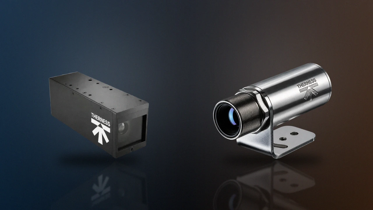
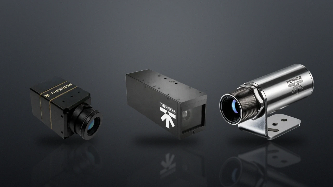
The HeatCam IR-C uses an uncooled LWIR microbolometer for continuous thermal monitoring at the weld station, covering the full preheat-to-interpass temperature range with no consumable cooling gas. For compact and embedded applications such as additive deposition, the HeatCam IR-S covers the same band in a smaller envelope, and the dedicated comparison of welding camera vs thermal camera explains where each modality belongs. To see the heat distribution an LWIR camera produces during a live weld, watch real-time thermal imaging of welding; the same thermal data also drives post-weld thermography NDT testing on finished components.
Resolution and Frame Rate Requirements by Process
Resolution and frame rate must be matched to your process, not maximised in the abstract. Over-specifying both inflates cost and data volume without improving the measurement, while under-specifying frame rate blurs the very pool dynamics you wanted to observe.
| Process | Typical travel speed | Minimum frame rate | Useful pool resolution |
|---|---|---|---|
| GMAW robotic | 400–800 mm/min | 25–60 fps | 0.1–0.3 mm/px |
| FCAW semi-automatic | 200–500 mm/min | 25 fps | 0.3–0.5 mm/px |
| SAW column and boom | 300–600 mm/min | 25 fps | 0.5–1.0 mm/px |
| Laser hybrid | 1500–5000 mm/min | 200–500 fps | 0.05–0.1 mm/px |
| TIG precision | 50–200 mm/min | 25 fps | 0.1–0.2 mm/px |
For LWIR thermal cameras, 25 to 60 fps is sufficient for all arc welding processes because thermal gradients evolve over seconds, not milliseconds. High-speed thermal imaging is not required for standard interpass and preheat monitoring.
The relationship between travel speed, frame rate, and motion blur is the same one studied in high-speed photography: to freeze a moving feature you need both a short exposure and a frame interval shorter than the time the feature takes to traverse one resolution element. For a weld pool moving at 5 m/min, a single pixel of 0.1 mm is traversed in roughly 1.2 ms, so a 25 fps camera (40 ms interval) smears the pool across more than 30 pixels — which is why high-speed visual capture matters for laser-hybrid processes. A practical walk-through of selecting these parameters for a real installation is given in the camera specs, setup and integration guide.
For additive and wire-arc deposition, where layer-by-layer thermal history is critical, the requirements shift again; the WAAM additive manufacturing monitoring overview describes how both visual and thermal capture combine in those cells.
Illumination and Laser Safety
A weld pool camera requires an active illumination source. Purpose-built systems use a high-power LED or solid-state illuminator in a narrow wavelength band (typically 808 to 980 nm near-infrared). The illumination power needed to overcome ambient arc emission is substantial, and that power is what makes laser safety a hard procurement gate rather than a footnote.
This is a non-negotiable safety specification. Verify before purchase:
- Safety class of the illumination source per IEC 60825-1: Class 1 or 1M limits accessible emission via the optics; Class 3R, 3B, and 4 require progressively stricter enclosures, interlocks, and administrative controls.
- Enclosure and interlock design: the illumination path must be enclosed so that stray radiation cannot exit the fixture toward operators or bystanders.
- CE marking and compliance documentation if deploying in Europe, and an evaluation of workplace exposure consistent with the radiation-safety guidance published by OSHA and the radiometric framework maintained by NIST.
Design guardrail — verify, do not assume. A “laser-safe” claim means nothing without classification data at your intended working distance. Ask the vendor for the accessible-emission-limit calculation and the test report under IEC 60825-1, not a marketing label. A source that is Class 1 at 1 m may be hazardous at 200 mm — the distance where a maintenance technician actually works on the cell.
The Therness PoolDrop uses a laser-safe illumination design that meets Class 1 requirements in normal operating conditions — no exposed high-power beam path, no operator-facing radiation hazard — while delivering sufficient power to image the molten pool at GMAW and FCAW travel speeds. Independent technical guidance on in-process monitoring safety and validation is published by TWI Global, which is a useful neutral reference when writing your own acceptance criteria.
Integration Requirements: Data Output and Process Control
A welding camera that produces images no one looks at adds no value. Integration determines whether the system reaches production impact, and it is the dimension buyers most often underestimate when comparing two cameras with similar optical specifications.
- Does the system output quantified parameters (pool width, temperature values) or only video streams?
- What communication interfaces are available: Ethernet, Modbus, OPC-UA, analog 4–20 mA?
- Can alarms trigger an arc stop or conveyor pause on the robot controller?
- Does the system timestamp data to weld seam position (encoder or robot TCP)?
- Is data logged per joint with unique weld IDs traceable to your QMS?
- What is the export format for traceability records under your applicable welding standard?
A system that outputs only MJPEG or H.264 video requires a separate analytics pipeline to extract process parameters. Systems that output quantified process data (pool area, peak temperature, HAZ width) directly can feed into an existing MES or QMS with minimal integration effort.
For thermographic inspection procedures or railway and pressure-equipment certification documentation, the camera system’s data export must be audit-ready: timestamped, traceable to weld joint ID, and exportable in a format your certification body accepts. The structure of an interoperable data interface — and why OPC-UA has become the default for this layer — is described in the reference on OPC Unified Architecture. When the camera lives on a robot arm, cable management, TCP synchronisation, and controller handshaking become as important as the optics; the camera for robotic welding cells integration guide covers that integration layer end to end, and HeatCore AI shows how quantified camera output drives closed-loop process control.
Common Specification Pitfalls and Failure Modes
The pitfalls below account for the majority of welding camera procurements that disappoint in service. Each maps to a root cause you can check before signing a purchase order.
| Pitfall | Symptom in service | Root cause | What to verify before purchase |
|---|---|---|---|
| Megapixels over dynamic range | Saturated white frames during the arc | High pixel count, low full-well/dynamic range | Sensor dynamic range (dB) and filter FWHM, not resolution |
| Camera bought without optics | Out-of-focus or wrong field of view at install | Optics, working distance, and housing not part of the quote | Complete installation envelope: lens, housing, air purge |
| Wrong thermal band | Inaccurate temperature, emissivity errors | SWIR or NIR sensor used where LWIR is validated | Confirm 8–14 µm LWIR for arc preheat/interpass |
| Underestimated data volume | Storage fills, frames dropped | Raw-frame retention not designed in | Decide raw vs processed-parameter retention up front |
| No arc-on evaluation | Looks great in demo, fails at the cell | Filter isolation never tested under real arc | Require arc-on footage at your current and gas |
| Optical window neglect | Image darkens over a shift | Spatter/fume on window, no purge or quick-change | Air-purge spec and tool-free window replacement |
A 25 fps camera running 16 hours per day generates roughly 1.4 million frames; decide at procurement whether raw frames are retained or only processed parameters, because storage architecture is part of the system specification, not an afterthought. And always request a live or recorded demonstration of the camera operating with the arc running — arc-off images are meaningless for evaluating filter isolation and dynamic range. If a vendor cannot provide arc-on footage representative of your process, treat that as a red flag and ask for a coupon trial instead.
Many production environments benefit from both modalities deployed together: the thermal camera covers preheat and interpass compliance continuously, while the visual pool camera monitors geometry for process fault detection at the same station. The relative strengths are summarised below.
| Criterion | Visual (CCD/CMOS + filter) | LWIR Thermal |
|---|---|---|
| Weld pool geometry | Yes | No |
| Quantified temperature | No (intensity only) | Yes (calibrated) |
| Arc saturation immunity | Yes (with correct filter) | Yes (LWIR band) |
| Preheat / interpass evidence | No | Yes |
| Procedure-compliance evidence | Not applicable | Direct evidence |
| Thermography inspection | Not applicable | Yes |
| High-speed laser process control | Yes (200+ fps capable) | Not required |
| Integration complexity | Medium (video + analytics) | Low–Medium |
Step-by-Step Camera Evaluation Procedure
Before committing to any welding camera, run a structured evaluation rather than trusting the datasheet. The five steps below turn a subjective demo into a defensible procurement decision.
Step 1 — Define the Measurement and Acceptance Criteria
Write down the process variable (geometry, arc, or temperature), the required accuracy, the travel speed, and the standard you must satisfy. Convert each into a measurable acceptance criterion — for example, “pool width resolved to ±0.2 mm at 600 mm/min” or “interpass temperature accurate to ±2°C at 250°C.” Without quantified criteria, every camera looks acceptable in a demo.
Step 2 — Screen on Dynamic Range, Filter, and Band
Reject any visual camera that cannot state its dynamic range in dB and its filter FWHM in nm, and any thermal camera that does not operate in the 8 to 14 µm LWIR band with a stated NETD. This single screen eliminates most unsuitable hardware before you invest test time.
Step 3 — Run an Arc-On Coupon Test at Your Parameters
Set up a representative coupon at your nominal current, shielding gas, and travel speed. Capture at least 100 arc-on frames. For a visual camera, confirm the weld pool boundary is visible in more than 90% of frames and that fewer than 5% of pool-region pixels are saturated. For a thermal camera, verify the measured temperature against a calibrated contact reference at two points in your working range.
Step 4 — Verify Laser Safety and Environmental Survival
Obtain the IEC 60825-1 classification report at your working distance, confirm the housing IP rating against IEC 60529 for your environment, and check the rated continuous operating temperature. Inspect the air-purge provision and confirm the optical window can be replaced without tools. The applicable codes and conformity-assessment documents can be located through ANSI’s standards store.
Step 5 — Validate Integration and Traceability
Connect the camera to your controller or MES over the intended interface (OPC-UA, Modbus, or 4 to 20 mA) and confirm that an alarm can trigger an arc stop, that data is timestamped to weld position, and that records export per joint in a format your QMS and certification body accept. Only when all five steps pass is the camera ready for a purchase decision.
Document every step with date, operator, and measured values so the evaluation itself becomes an auditable record. If you want a second opinion on mapping these steps to your specific process, our team offers welding process consulting, and the welding camera resources hub collects the datasheets and validation templates referenced throughout this guide.
FAQ
What is the most important specification in a welding camera buyer guide?
Dynamic range and filter isolation, not megapixel count. In an arc environment a 2 MP sensor with 120 dB dynamic range and a 10 nm FWHM narrowband filter produces a usable weld pool image, while a 12 MP sensor without arc attenuation saturates and shows nothing. Always evaluate sensor dynamic range and optical filtering before resolution.
Should I buy a visual camera or a thermal camera for welding?
It depends on what you measure. Visual CCD/CMOS cameras image weld pool geometry and arc behaviour and are best for real-time process fault detection. LWIR thermal cameras quantify temperature and are best for preheat, interpass, and heat-affected-zone compliance. Many production cells deploy both at one station because no single modality covers geometry and calibrated temperature with equal fidelity.
What frame rate does a welding camera need?
Frame rate scales with travel speed. Standard GMAW at 400 to 800 mm/min is well served by 25 to 60 fps for geometry trending. High-speed laser-hybrid welding at 1.5 to 5 m/min needs 200 fps or more to resolve pool dynamics. LWIR thermal monitoring runs comfortably at 25 to 60 fps because thermal gradients evolve over seconds, not milliseconds.
What laser safety class should a weld camera illuminator meet?
Verify the illumination source classification under IEC 60825-1. Class 1 or 1M designs limit accessible emission so there is no operator-facing hazard in normal operation. Class 3R, 3B, or 4 sources require enclosures, interlocks, and administrative controls. Ask the vendor for classification data at your working distance and CE marking documentation for European deployment, not just a marketing claim.
How do I know if a welding camera will survive my arc environment?
Check the housing IP rating against IEC 60529 (IP54 minimum for spatter and grinding dust, IP67 for wash-down), the rated continuous operating temperature, and the air-purge and optical-window provisions. Confirm the rating applies to the complete assembly including the optical window seal, and request IP test certificates rather than relying on datasheet declarations.
What integration interfaces should a welding camera support?
For production process control, look for Ethernet, Modbus TCP, OPC-UA, or analog 4 to 20 mA outputs, the ability to trigger an arc stop or conveyor pause on the robot controller, timestamping to weld seam position, and per-joint logging with unique weld IDs traceable to your QMS. A system that outputs only MJPEG or H.264 video needs a separate analytics pipeline before it delivers process data.
Why does the buyer guide warn against specifying megapixels?
High pixel count does nothing if the sensor saturates on arc radiation. Resolution only matters once the camera can form a non-saturated image, which depends on dynamic range, the narrowband filter, and matched illumination. A high-resolution sensor with insufficient dynamic range delivers uniformly white, unusable frames during the arc-on phase.
Can I evaluate a welding camera from arc-off images alone?
No. Arc-off images reveal nothing about filter isolation or dynamic range under the real disturbance. Always require a live or recorded arc-on demonstration representative of your process, shielding gas, and current. If a vendor cannot supply arc-on footage at your parameters, treat that as a procurement red flag and request a coupon trial.
Ready to specify your welding monitoring system?
Book a technical consultation to review your process requirements, mounting constraints, and integration targets — thermal, visual, or both — before committing to hardware. We can map this buyer guide to your exact arc parameters, travel speed, and compliance requirements.
Book a demoTherness solution: Welding camera — Thermal and high-speed imaging that watches the arc, the pool and the cooling seam while the weld is made.
Frequently Asked Questions
What is the most important specification in a welding camera buyer guide?
Dynamic range and filter isolation, not megapixel count. In an arc environment, a 2 MP sensor with 120 dB dynamic range and a 10 nm FWHM narrowband filter produces a usable weld pool image, while a 12 MP sensor without arc attenuation saturates and shows nothing. Always evaluate sensor dynamic range and optical filtering before resolution.
Should I buy a visual camera or a thermal camera for welding?
It depends on what you measure. Visual CCD/CMOS cameras image weld pool geometry and arc behaviour and are best for real-time process fault detection. LWIR thermal cameras quantify temperature and are best for preheat, interpass, and heat-affected-zone compliance. Many production cells deploy both at one station because no single modality covers geometry and calibrated temperature with equal fidelity.
What frame rate does a welding camera need?
Frame rate scales with travel speed. Standard GMAW at 400 to 800 mm per minute is well served by 25 to 60 fps for geometry trending. High-speed laser-hybrid welding at 1.5 to 5 m per minute needs 200 fps or more to resolve pool dynamics. LWIR thermal monitoring runs comfortably at 25 to 60 fps because thermal gradients evolve over seconds, not milliseconds.
What laser safety class should a weld camera illuminator meet?
Verify the illumination source classification under IEC 60825-1. Class 1 or 1M designs limit accessible emission so there is no operator-facing hazard in normal operation. Class 3R, 3B, or 4 sources require enclosures, interlocks, and administrative controls. Ask the vendor for classification data at your working distance and CE marking documentation for European deployment, not just a marketing claim.
How do I know if a welding camera will survive my arc environment?
Check the housing IP rating against IEC 60529 (IP54 minimum for spatter and grinding dust, IP67 for wash-down), the rated continuous operating temperature, and the air-purge and optical-window provisions. Confirm the rating applies to the complete assembly including the optical window seal. Request IP test certificates rather than relying on datasheet declarations.
What integration interfaces should a welding camera support?
For production process control, look for Ethernet, Modbus TCP, OPC-UA, or analog 4 to 20 mA outputs, the ability to trigger an arc stop or conveyor pause on the robot controller, timestamping to weld seam position, and per-joint logging with unique weld IDs traceable to your QMS. A system that outputs only MJPEG or H.264 video needs a separate analytics pipeline before it delivers process data.
Why does the buyer guide warn against specifying megapixels?
High pixel count does nothing if the sensor saturates on arc radiation. Resolution only matters once the camera can form a non-saturated image, which depends on dynamic range, the narrowband filter, and matched illumination. A high-resolution sensor with insufficient dynamic range delivers uniformly white, unusable frames during the arc-on phase.
Can I evaluate a welding camera from arc-off images alone?
No. Arc-off images reveal nothing about filter isolation or dynamic range under the real disturbance. Always require a live or recorded arc-on demonstration representative of your process, shielding gas, and current. If a vendor cannot supply arc-on footage at your parameters, treat that as a procurement red flag and request a coupon trial.