Passive thermal monitoring tells you that a weld is hot. Active thermography tells you what is hiding inside it.
For decades, inspectors have relied on post-weld NDT methods—radiographic testing (RT), phased-array ultrasonic testing (PAUT), magnetic particle testing (MT)—to find subsurface defects such as porosity, lack of fusion, and cold cracks. These methods are precise, but they are also slow, require trained specialists, involve contact or coupling agents, and deliver their verdict only after the weld has already cooled and the part has moved down the production line.
Active thermography breaks that model. By exciting the weld zone with a controlled thermal stimulus—a flash lamp, an induction coil, a modulated laser—and then recording the transient thermal response with an infrared camera, the technique reveals subsurface anomalies during or immediately after welding, without contact and at production speed.
This guide explains the physics, the four main variants, the relevant standards, and how to integrate active thermographic inspection into a compliant welding quality workflow.
What Is Active Thermography and Why Does It Matter for Welds?
Thermographic testing is an established non-destructive testing discipline that uses infrared cameras to detect temperature anomalies on or below the surface of a component. In passive mode the camera simply observes heat generated by the process itself—useful for monitoring arc stability and heat input but limited in its ability to distinguish subsurface voids from surface geometry.
Active thermography adds a second element: a controlled energy excitation. When a pulse of heat flows into a sound material, the temperature rises and decays uniformly. Where a subsurface void, inclusion, or crack interrupts that heat flow, the surface above it behaves differently—warming more slowly, retaining heat longer, or generating a measurable phase shift. The IR camera captures these anomalies frame by frame.
Key distinction: Passive thermography monitors the weld process. Active thermography inspects the weld product. Most high-integrity applications need both.
The industrial case is compelling:
- Speed: Pulsed thermography can inspect a 200 mm weld bead in under 10 seconds, compared with minutes for PAUT with encoder scanning.
- No contact: No coupling gel, no probe pressure, no masking for magnetic particle testing.
- Full-field imaging: A single thermal image covers the entire weld and heat-affected zone simultaneously.
- Digital evidence: Every inspection produces a calibrated radiometric image sequence—a permanent, traceable record compatible with ISO 3834-2:2021 documentation requirements.
The Four Active Thermography Variants Used in Weld Inspection
The choice of excitation method determines which defect types are detectable, at what depth, and at what line speed. Understanding the physics of each variant is essential before specifying a system.
1. Pulsed Thermography (PT)
A short, intense burst of energy—typically from flash lamps or an IR heater—heats the surface of the weld for a few milliseconds to seconds. The camera records the subsequent cooling at high frame rate.
Physics: Subsurface defects act as thermal barriers. The time at which the temperature contrast above a defect reaches its maximum is proportional to the square of the defect depth divided by thermal diffusivity. This relationship allows quantitative depth estimation without calibration blocks.
Best for: Shallow subsurface porosity (up to ~5 mm in steel), delaminations, inclusions. Fast enough for inline use on welds that have cooled to below ~200 °C.
Limitation: Sensitivity decreases with depth. Not suitable for deep hydrogen cracks in thick-section structural welds without longer excitation pulses.
2. Lock-In Thermography (LIT)
Instead of a single pulse, the excitation source is modulated at a fixed frequency—typically 0.01–10 Hz. The camera records at the same frequency and a lock-in algorithm extracts the phase and amplitude of the thermal response at each pixel.
Physics: The phase image is largely independent of local emissivity variations and surface geometry—a significant advantage when inspecting welds with variable surface roughness or spatter. The penetration depth scales with the thermal diffusion length, which decreases at higher modulation frequencies. By sweeping frequency, different depth layers can be interrogated.
Best for: Detecting subsurface cracks in metallic welds with surface emissivity variation, corrosion beneath coatings, disbonds in clad materials, and HAZ microstructural changes in stainless steel.
Lock-in thermography’s phase image suppresses emissivity noise—making it the preferred method when weld spatter or oxidation creates non-uniform surface conditions.
3. Induction Thermography
An alternating electromagnetic field induces eddy currents in the conductive workpiece. Eddy current density concentrates around surface and near-surface defects, creating local heating that is captured by the IR camera.
Physics: The current concentrates at the surface (skin depth) and flows around cracks, producing resistive heating at the crack edges. This makes induction thermography uniquely sensitive to surface-breaking and near-surface cracks—the category most critical in pressure vessel, pipeline, and structural steel welds.
Best for: Surface and near-surface longitudinal and transverse cracks, heat-check cracks, HAZ micro-cracks. Used in automotive BIW resistance spot weld inspection and pipeline girth weld monitoring.
Integration note: Induction coil geometry must be optimised for weld orientation. Linear coils suit longitudinal seam welds; circular coils suit circumferential pipe welds.
4. Laser Thermography
A scanned laser spot or line delivers heat at high spatial resolution. The resulting thermal wave propagates into the material and the backscattered thermal signal is captured by the IR camera.
Best for: High-resolution mapping of very shallow cracks and surface-connected defects in complex geometries, additive manufacturing builds, and laser welds with narrow beads. Well-suited for EV battery tab welding inspection where spatial resolution matters.
Standards Governing Active Thermographic NDT
Thermographic testing in industrial and construction applications is governed by two key standards that purchasing and quality teams need to know.
EN 16714 – Non-destructive testing: Thermographic testing is the European standard published by CEN/TC 138, comprising three parts: general principles (Part 1), equipment (Part 2), and terms and definitions (Part 3). It defines how thermographic inspection is planned, executed, and reported, including choice of excitation method, camera requirements, and documentation.
ISO 9712:2021 – Non-destructive testing: Qualification and certification of NDT personnel includes thermographic testing (TT) among the ten recognised NDT methods. Personnel performing active thermographic weld inspection must hold a valid ISO 9712 TT Level 2 or Level 3 certification from an approved body to issue inspection reports accepted by auditors under ISO 3834, EN 1090, and ASME standards.
ISO 17635:2016 – Non-destructive testing of welds: General rules for metallic materials provides the overarching framework for selecting and applying NDT methods to welds. While it does not mandate thermography specifically, it defines the general principles—inspection coverage, acceptance criteria referencing ISO 5817, documentation—that an active thermographic procedure must satisfy.
Compliance checklist for active thermographic weld inspection:
- Procedure written per EN 16714 Part 1
- Equipment meets EN 16714 Part 2 (NETD, frame rate, field of view)
- Inspector holds ISO 9712 TT Level 2+ certification
- Inspection records linked to WPS/PQR via ISO 3834-2 traceability chain
- Acceptance criteria defined per ISO 5817 or applicable product standard
Defect Types Detectable with Active Thermography
Active thermography is not a universal replacement for all NDT methods—but its detection capability covers the most common and most costly weld defects.
| Defect Type | PT | LIT | Induction | Laser |
|---|---|---|---|---|
| Subsurface porosity (≤5 mm) | ✅ | ✅ | ⚠️ | ⚠️ |
| Lack of fusion / incomplete penetration | ✅ | ✅ | ✅ | ✅ |
| Longitudinal surface cracks | ⚠️ | ✅ | ✅ | ✅ |
| Transverse cracks | ⚠️ | ✅ | ✅ | ✅ |
| Inclusions | ✅ | ✅ | ⚠️ | ⚠️ |
| HAZ micro-cracking | ❌ | ✅ | ✅ | ✅ |
| Corrosion / wall thinning | ✅ | ✅ | ❌ | ⚠️ |
✅ = primary method | ⚠️ = possible with optimised setup | ❌ = not recommended
For detection of deep hydrogen-induced cold cracks (>10 mm in thick-section steels), ultrasonic TOFD or PAUT remains the method of choice. Active thermography is most powerful as a complementary, first-pass inspection that flags anomalies for targeted follow-up.
Integrating Active Thermography into a Production Welding Line
The practical question is not whether active thermography works in a laboratory—it does, across decades of published research—but how to implement it in a production environment where robots move fast, surfaces are hot, and the quality system demands traceable records. Therness engineers subsurface inspection built around stimulated heat for exactly that production reality.
Step 1 — Define the inspection window
Active thermography requires the weld to be below approximately 200 °C for pulsed and lock-in methods (to ensure the excitation signal is distinguishable from residual process heat). In practice, this means either:
- Post-cell inspection station: A dedicated station downstream where parts cool on a conveyor. Typical cycle time: 30–120 seconds depending on weld mass. Fits most automotive BIW and structural fabrication lines.
- End-of-pass inspection: For multi-pass welds, each completed pass can be inspected before the next is deposited. This integrates naturally with robotic MIG/MAG and orbital TIG processes.
- Induction thermography during welding: Induction excitation can be applied very close to the weld pool on resistance spot welds, enabling near-real-time crack detection without waiting for cooling.
Step 2 — Select and qualify the excitation/camera system
Key camera parameters per EN 16714 Part 2:
- NETD (noise-equivalent temperature difference): ≤50 mK for metallic welds with pulsed excitation; ≤20 mK for lock-in phase imaging.
- Frame rate: Minimum 25 Hz for pulsed; 1–5 Hz for lock-in at low modulation frequencies.
- Spectral range: MWIR (3–5 µm) for high-temperature surfaces; LWIR (8–14 µm) for cooled welds at ambient temperature.
- Spatial resolution: Sufficient to resolve the minimum detectable flaw size per the applicable acceptance standard.
System qualification should include reference blocks with calibrated artificial defects (flat-bottom holes or EDM notches) at the target depth to demonstrate probability of detection (POD) for the specified flaw size. Therness supplies the IR inspection hardware — camera, excitation head, and processing — matched to these parameters.
Step 3 — Write the thermographic procedure
The procedure (analogous to a WPS in welding) must define:
- Material type, thickness, and weld joint configuration
- Excitation method, source parameters (energy, pulse duration or frequency), and standoff distance
- Camera type, lens, frame rate, and recording duration
- Post-processing algorithm (peak contrast, phase extraction, principal component analysis)
- Scan pattern and coverage
- Acceptance/rejection threshold
This procedure is submitted for third-party review if the inspection supports acceptance to pressure vessel, structural, or aerospace codes.
Step 4 — Connect to QMS for traceability
Every active thermographic inspection record—the raw thermal sequence, the processed defect map, the pass/fail decision—must be linked to the weld identifier, WPS reference, operator/robot ID, and timestamp. This data chain satisfies the documentary requirements of ISO 3834-2:2021 and provides the evidence pack an auditor needs to verify that every weld was inspected.
Digital QMS platforms can ingest thermographic output files via API and automatically attach them to the correct work order, generating a complete weld history file without manual transcription—eliminating one of the largest sources of documentation error in welding quality programmes.
See How HeatCore Integrates Active Thermographic Data into Your QMS
HeatCore captures thermal sequences, applies AI-based defect classification, and feeds structured inspection records directly into your quality management workflow—meeting ISO 3834, EN 1090, and ASME documentation requirements automatically.
Book a demoActive vs Passive Thermography: Choosing the Right Mode
Many welding monitoring systems sold today operate in passive mode—the IR camera observes the weld pool and bead cooling without any additional excitation. This is valuable for real-time process control: detecting arc instability, measuring heat input, identifying gross porosity from gas pockets in the melt pool. But it does not constitute NDT inspection for subsurface defects in the finished weld.
The two modes are complementary, not competing (see how this applies to laser welding monitoring for EV battery manufacturing):
- Passive thermography during welding → process monitoring, heat input control, weld pool geometry feedback, real-time alarm on gross anomalies
- Active thermography after welding → subsurface defect inspection, NDT evidence record, compliance with inspection standards
A complete quality assurance strategy deploys both. The passive layer catches problems early enough to intervene (stop the robot, adjust parameters). The active layer provides the mandatory inspection evidence that the finished weld meets the specified acceptance criteria. (See a side-by-side thermal imaging weld comparison.)
This two-layer approach aligns with the quality assurance levels defined in ISO 3834-2:2021, which requires both process monitoring and non-destructive testing of finished welds for the comprehensive quality requirement level.
Common Implementation Challenges and How to Solve Them
Challenge: Variable surface emissivity from spatter and oxidation Solution: Use lock-in thermography (phase image is emissivity-independent) or apply a thin, uniform matte coating to the inspection area. Calibrate with a reference sample of known emissivity.
Challenge: Hot parts entering the inspection station above 200 °C Solution: Add a forced-air or water-mist cooling stage between welding and inspection. Alternatively, use induction thermography which can operate closer to elevated temperatures.
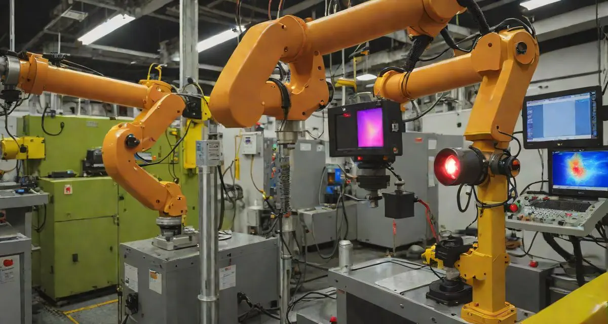
Challenge: Geometric complexity (pipe saddles, T-joints, complex surface profiles) Solution: Use a robotic arm to scan the excitation source and camera together around the joint, or use laser thermography with flexible scanning optics.
Challenge: Justifying inspection cycle time in a takt-limited line Solution: Parallel inspection stations for multiple parts, and statistical acceptance sampling (per ISO 17635 criteria) for low-criticality welds, reserving 100% inspection for safety-critical joints.
Challenge: Creating compliant inspection procedures without in-house NDT expertise Solution: Partner with a Level 3 ISO 9712 TT-certified body to write and qualify the procedure. The procedure becomes a reusable asset; ongoing inspections are performed by Level 2 operators trained to it.
Return on Investment: The Case for Active Thermographic NDT
The business case for active thermographic inspection rests on three cost categories.
1. Defect escape cost reduction. A subsurface lack-of-fusion defect that passes visual inspection and escapes to a customer site can trigger recalls, rework campaigns, and liability claims that dwarf the cost of an inspection system. In automotive, a single warranty field failure from a structural weld can carry six-figure direct costs before legal exposure.
2. Post-weld NDT cost displacement. A robotic pulsed thermography cell operating at 20 seconds per weld can replace a significant portion of manual RT or PAUT inspection, reducing consumables (X-ray film, coupling gel), radiation safety costs, and skilled inspector time.
3. Scrap and rework reduction at source. When active thermography is deployed as first-pass inspection before final machining or assembly, defective welds are caught while rework is still economical—before downstream value has been added. The earlier in the process a defect is caught, the lower the cost of rejection.
For fabricators operating under ISO 3834-2:2021 comprehensive quality requirements, active thermographic NDT is not just an efficiency tool—it is a systematic response to the standard’s requirement for a defined, documented, and repeatable inspection programme.
Summary: When Active Thermography Is the Right Choice
Active thermography is the right NDT choice when:
- Subsurface detection is required beyond what visual or surface NDT methods provide
- Production throughput matters and manual PAUT/RT would create a bottleneck
- Digital traceability is mandatory under ISO 3834, EN 1090, ASME, or customer quality plans
- Contact is impractical (hot surfaces, inaccessible geometry, or contamination risk)
- Weld geometry allows full-field imaging without complex scanning mechanics
- Defect depth is ≤10 mm in structural steels, or surface/near-surface in all materials
Combining active thermographic inspection with a real-time passive monitoring system—and connecting both data streams to a digital QMS—creates the most complete, auditable, and commercially defensible welding quality programme available today.
Related Reading
- Infrared Thermography for Welding: Real-Time Quality Control Guide
- AI Weld Defect Detection: Thermal vs Vision vs Acoustic—Which Method Fits Your Process?
- Welding Inspection Methods Compared: Visual, RT/UT/PAUT, and Real-Time Monitoring
- ISO 3834 & EN 1090 Compliance: Digital Welding Traceability
- SPC for Welding: Control Charts, Cpk, and Thermal Limits
Therness solution: Welding monitoring system — Every weld inspected in the cycle, with defect flags and the ISO 3834 / ISO 17635 evidence kept per weld.