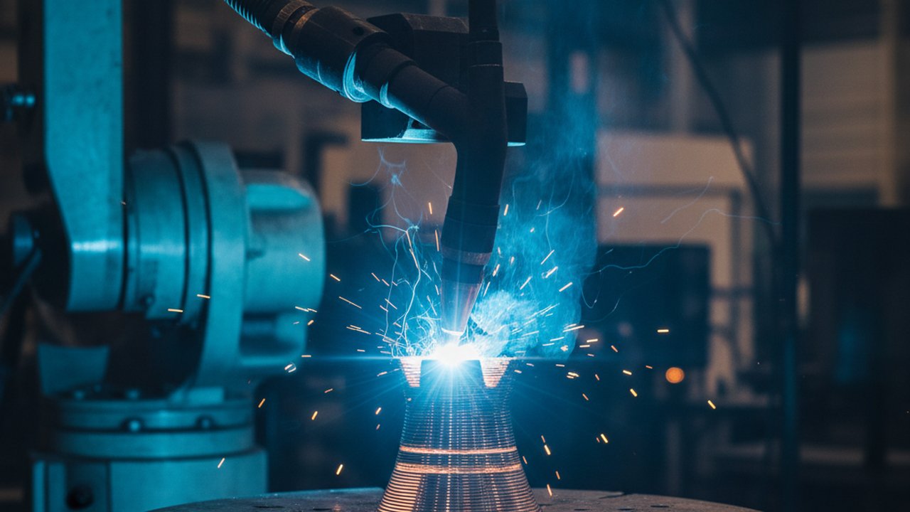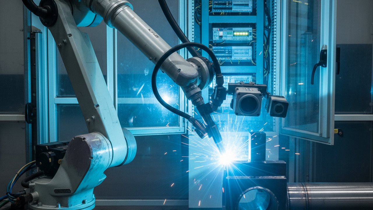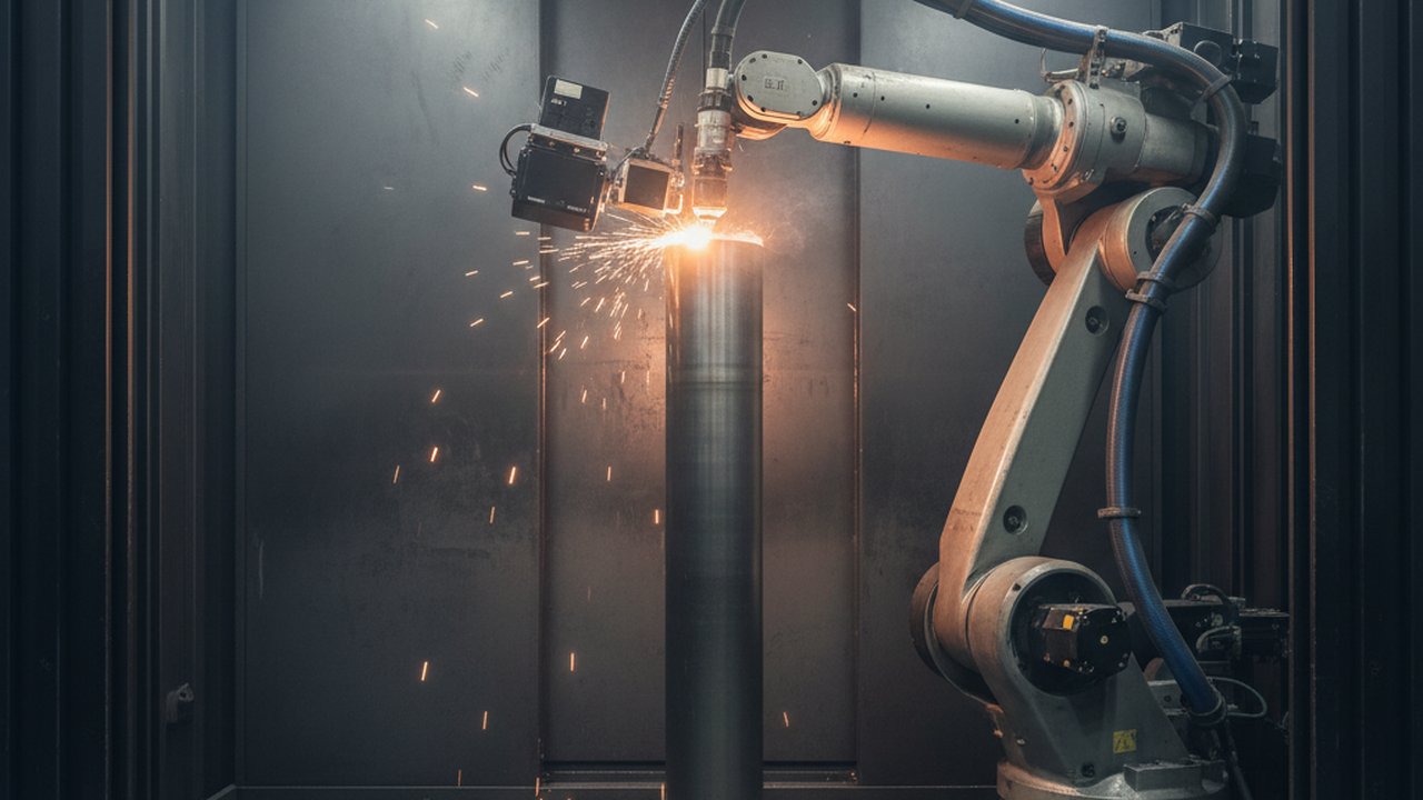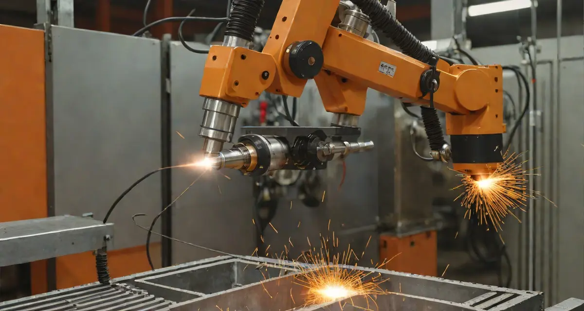
Cold wire feeding welding thermal monitoring is transforming how manufacturers approach automated deposition processes. Unlike hot wire TIG systems that preheat filler material, cold wire feeding introduces filler at ambient temperature directly into the welding arc—offering distinct advantages for precision applications in aerospace, nuclear, and high-performance manufacturing.
This guide examines how integrating thermal imaging with cold wire feed automation enables real-time quality control, optimizes deposition parameters, and ensures consistent weld geometry across production cycles.
What Is Cold Wire Feeding in Welding?
Cold wire feeding, also known as cold wire TIG (Gas Tungsten Arc Welding with cold wire addition), involves introducing filler wire at room temperature into the molten weld pool. The wire enters the arc zone adjacent to the tungsten electrode, where arc energy melts the filler material and base metal simultaneously.
Cold wire feeding differs fundamentally from hot wire TIG: no auxiliary power source heats the wire before deposition. The arc provides all thermal energy, simplifying equipment while requiring precise synchronization between wire feed rate and welding parameters.
Key Process Characteristics
| Parameter | Cold Wire Feeding | Hot Wire TIG |
|---|---|---|
| Wire temperature | Ambient (~20°C) | Preheated (200-400°C) |
| Equipment complexity | Lower | Higher |
| Deposition rate | 1.5–4.0 kg/hr | 3.0–8.0 kg/hr |
| Heat input control | Direct via arc parameters | Combined arc + wire heating |
| Application focus | Precision, thin materials | High deposition, thick sections |
| Cost | Lower capital investment | Higher equipment cost |
The moderate deposition rates of cold wire systems make them ideal for applications demanding exceptional bead appearance, minimal distortion, and precise heat-affected zone control—common requirements in aerospace welding and medical device manufacturing.
Why Thermal Monitoring Matters for Cold Wire Automation
Automated cold wire feeding systems operate at speeds and consistency levels impossible for manual welders. However, this automation introduces new quality risks: wire feed variations, arc length fluctuations, and joint fit-up inconsistencies can all affect deposition quality without immediate operator awareness.
Thermal imaging addresses these challenges by providing:
1. Real-Time Pool Temperature Measurement
The molten weld pool temperature directly indicates energy input sufficiency. Pool temperatures below optimal range suggest insufficient arc energy relative to wire feed rate—potentially causing lack of fusion or cold lap defects. Excessive temperatures indicate overheating, risking burn-through in thin materials or HAZ embrittlement in sensitive alloys. (See real-time thermal imaging of a live weld pool.)
Target pool temperatures vary by material:
- Carbon steel: 1450–1600°C
- Stainless steel (300 series): 1400–1550°C
- Nickel alloys: 1350–1500°C
- Titanium alloys: 1650–1800°C
- Aluminum alloys: 650–750°C
2. Wire Feed Synchronization Verification
Proper cold wire feeding requires the wire tip to enter the arc zone at precisely controlled intervals. Misalignment or inconsistent feed creates erratic arc behavior visible in thermal signatures. High-resolution thermal cameras detect these variations through pool shape changes and temperature fluctuations at 50+ Hz capture rates.
3. Deposition Consistency Tracking
Each weld pass must achieve target cross-sectional area and penetration depth. Weld bead geometry measurement through thermal profiles provides continuous verification without stopping production for destructive testing.
4. Defect Prevention Through Predictive Indicators
Cold wire feeding defects exhibit thermal precursors before visual manifestation:
- Tungsten inclusion risk: Electrode contamination appears as localized pool temperature spikes
- Porosity formation: Gas entrapment shows as asymmetric temperature distribution
- Lack of fusion: Insufficient interpass temperature creates distinct cooling patterns
- Excessive reinforcement: Overfeeding generates characteristic pool bulging visible thermally
Implementation Architecture for Cold Wire Systems
Deploying in-process weld monitoring for automated cells in cold wire feeding environments requires careful integration with existing automation infrastructure.
Sensor Positioning Strategies
The optimal thermal camera location depends on workpiece geometry and robot configuration:
Trailing View (Most Common) Camera positioned 150–300mm behind the torch, monitoring solidified bead and cooling profile. Captures bead width consistency and reveals heat input variations through cooling rate analysis.
Side View Orthogonal camera placement provides pool width and reinforcement height visibility. Particularly valuable for narrow groove applications where bead geometry control is critical.
Top-Down View Overhead mounting captures pool area and wire entry position. Ideal for orbital welding applications where torch orientation remains constant.
For multi-axis robotic systems, fixed-position cameras often outperform torch-mounted alternatives by eliminating motion blur and maintaining consistent calibration. Consider integrating multiple view angles for comprehensive coverage.
Integration with Welding Power Sources
Modern welding data historian MES integration enables correlation between thermal measurements and electrical parameters:
- Arc voltage: Correlates with arc length and travel speed
- Welding current: Determines energy input magnitude
- Wire feed speed (WFS): Directly affects deposition rate
- Travel speed: Combines with WFS to determine bead geometry
Synchronizing these data streams creates complete process documentation for ISO 3834 compliance and quality traceability.
Calibration for Cold Wire Environments
Cold wire operations present unique calibration challenges:
-
Emissivity compensation: Polished filler wire has different emissivity than oxidized base metal. Multi-point calibration across the weld zone improves accuracy.
-
Arc radiation shielding: The intense UV/visible radiation from GTAW arcs can affect some thermal sensors. Confirm your camera’s spectral filtering adequately rejects arc interference in the 0.4–1.0 μm range.
-
Spatter management: Although GTAW generates minimal spatter compared to GMAW, occasional tungsten spatter can contaminate protective windows. Implement automated air purge systems for continuous operation.
Optimizing Deposition Parameters with Thermal Feedback
The closed-loop control enabled by thermal monitoring allows dynamic parameter adjustment during welding.
Wire Feed Rate Optimization
Wire feed rate directly determines deposition rate in cold wire systems. However, simply maximizing WFS creates quality risks:
- Upper limit: Excessive wire feeding cools the pool, creating lack of fusion or irregular bead ripples
- Lower limit: Insufficient filler creates underfill and requires additional passes
Thermal monitoring enables WFS optimization by maintaining pool temperature within the target range. When pool temperature trends downward, the system can reduce WFS or increase current to restore thermal balance.
Heat Input Control per ISO 15614
Welding procedure specifications define acceptable heat input ranges. For cold wire feeding, the standard heat input formula applies:
Heat Input (kJ/mm) = (Voltage × Current × 60) / (Travel Speed × 1000)However, this calculation excludes thermal effects of introducing ambient-temperature filler. Actual heat distribution differs from autogenous welding at equivalent electrical parameters. Thermal imaging provides empirical verification that recorded heat input correlates with actual thermal cycles experienced by the material.
Interpass Temperature Management
Multi-pass cold wire welds require consistent interpass temperatures between layers. Thermal cameras monitor the underlying pass temperature as the torch approaches, enabling automatic travel speed adjustment or pause insertion when cooling rate requirements demand it.
This capability proves especially valuable for hydrogen-induced cracking prevention in high-strength steels, where thermal cycle control directly impacts susceptibility to delayed cracking.
Applications Across Industries
Cold wire feeding with thermal monitoring serves diverse industrial applications:
Aerospace Component Manufacturing
Titanium and nickel superalloy structures require exceptional cleanliness and precise heat input control. Titanium welding quality monitoring via thermal imaging ensures argon shielding effectiveness and detects contamination events through characteristic temperature signatures.
Nuclear Pressure Vessel Construction
ASME Section III requirements for nuclear components mandate comprehensive documentation. Thermal monitoring provides continuous verification that actual welding parameters remain within qualified ranges, supporting pressure vessel welding quality assurance under strict regulatory oversight.
Automotive Exhaust Systems
Thin-wall stainless steel tubing demands minimal heat input to prevent distortion. Cold wire TIG with thermal monitoring enables automated production of consistent, aesthetic welds on catalytic converter housings and exhaust components.
Semiconductor Equipment
High-purity welding for vacuum chambers and gas delivery systems requires elimination of oxidation and contamination. Thermal monitoring detects arc wandering and shielding gas disruption before they compromise weld integrity.
Economic Analysis: ROI of Thermal Monitoring Integration
Investment in thermal monitoring for cold wire automation delivers measurable returns:
| Cost Factor | Without Monitoring | With Thermal Monitoring |
|---|---|---|
| Rework rate | 3–8% | 0.5–2% |
| Destructive testing | 2–5 samples per lot | 0.5–1 samples per lot |
| Parameter deviations detected | Post-weld inspection only | Real-time, 100% coverage |
| Documentation labor | Manual, 15–30 min per weld | Automated, negligible |
| Scrap from undetected defects | 0.5–2% of production | less than 0.1% of production |
Typical payback periods range from 6–18 months depending on production volume and material value. High-value alloys (titanium, Inconel) recover investment faster due to reduced scrap costs.
Future Developments in Cold Wire Monitoring
Emerging technologies will further enhance cold wire feeding thermal monitoring:
Machine Learning for Defect Prediction
AI weld defect detection algorithms trained on thermal signatures can predict defects milliseconds before they form, enabling predictive rather than reactive parameter adjustment.
Multi-Sensor Fusion
Combining thermal imaging with weld pool geometry analysis via laser profilometry provides comprehensive physical characterization of the deposition process, correlating surface appearance with internal thermal state.
Digital Twin Integration
Real-time thermal data feeds welding process digital twins, enabling virtual parameter optimization before physical trial runs. This accelerates procedure qualification for new joint configurations and materials.
Conclusion
Cold wire feeding welding thermal monitoring transforms automated deposition from a black-box process into a fully characterized, continuously optimized operation. By providing real-time visibility into pool dynamics, bead formation, and heat distribution, thermal imaging enables manufacturers to achieve the consistency and documentation rigor demanded by aerospace, nuclear, and medical device industries.
The moderate investment in thermal monitoring infrastructure pays dividends through reduced rework, minimized destructive testing, and enhanced quality assurance. Explore the HeatCore monitoring range to match a configuration to your cold wire cells. As automated welding adoption accelerates across manufacturing sectors, thermal monitoring will become standard equipment rather than optional enhancement.
Optimize Your Cold Wire Welding Automation
Discover how HeatCore integrates with your wire feeding systems to deliver real-time thermal monitoring and automated quality control.
Book a demoReferences
-
International Organization for Standardization. (2021). ISO 3834-2:2021 Quality requirements for fusion welding of metallic materials — Part 2: Comprehensive quality requirements. iso.org
-
American Welding Society. (2025). AWS D1.1/D1.1M:2025 Structural Welding Code — Steel. pubs.aws.org
-
International Organization for Standardization. (2021). ISO 15614-1:2017/Amd 1:2021 Specification and qualification of welding procedures for metallic materials — Welding procedure test — Part 1: Arc and gas welding of steels and arc welding of nickel and nickel alloys. iso.org
-
European Committee for Standardization. (2018). EN 1090-2:2018 Execution of steel structures and aluminium structures — Part 2: Technical requirements for steel structures. standards.cen.eu
Therness solution: Welding camera — Thermal and high-speed imaging that watches the arc, the pool and the cooling seam while the weld is made.