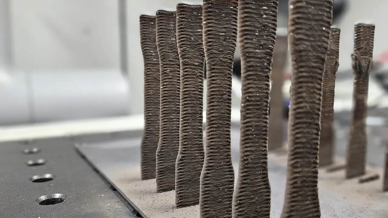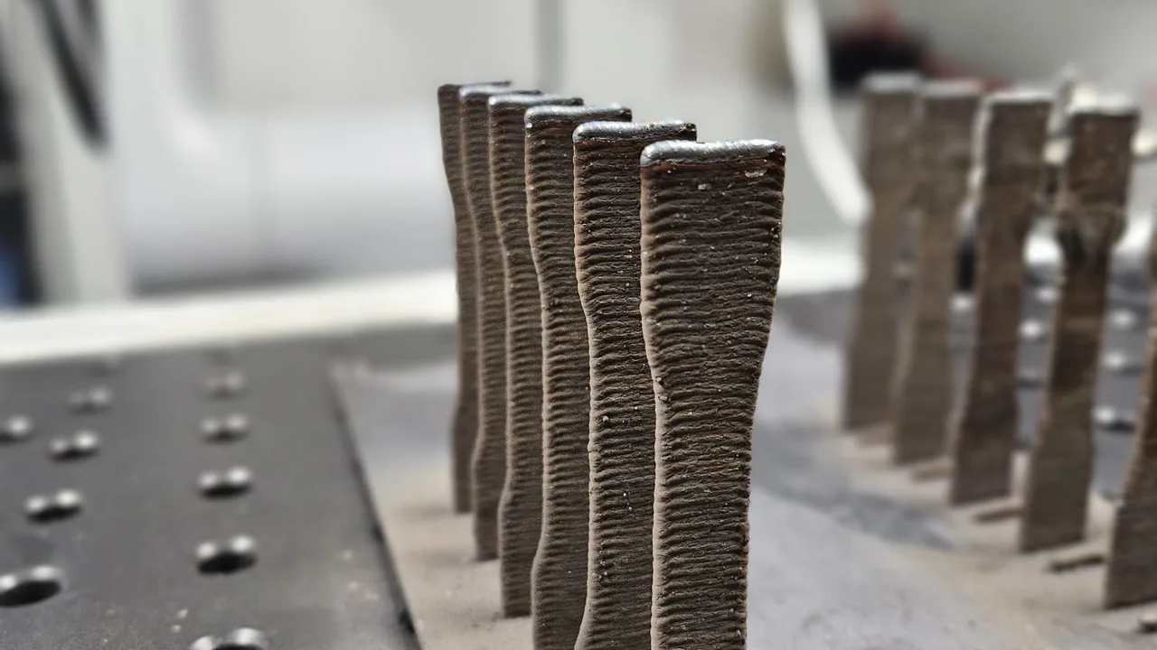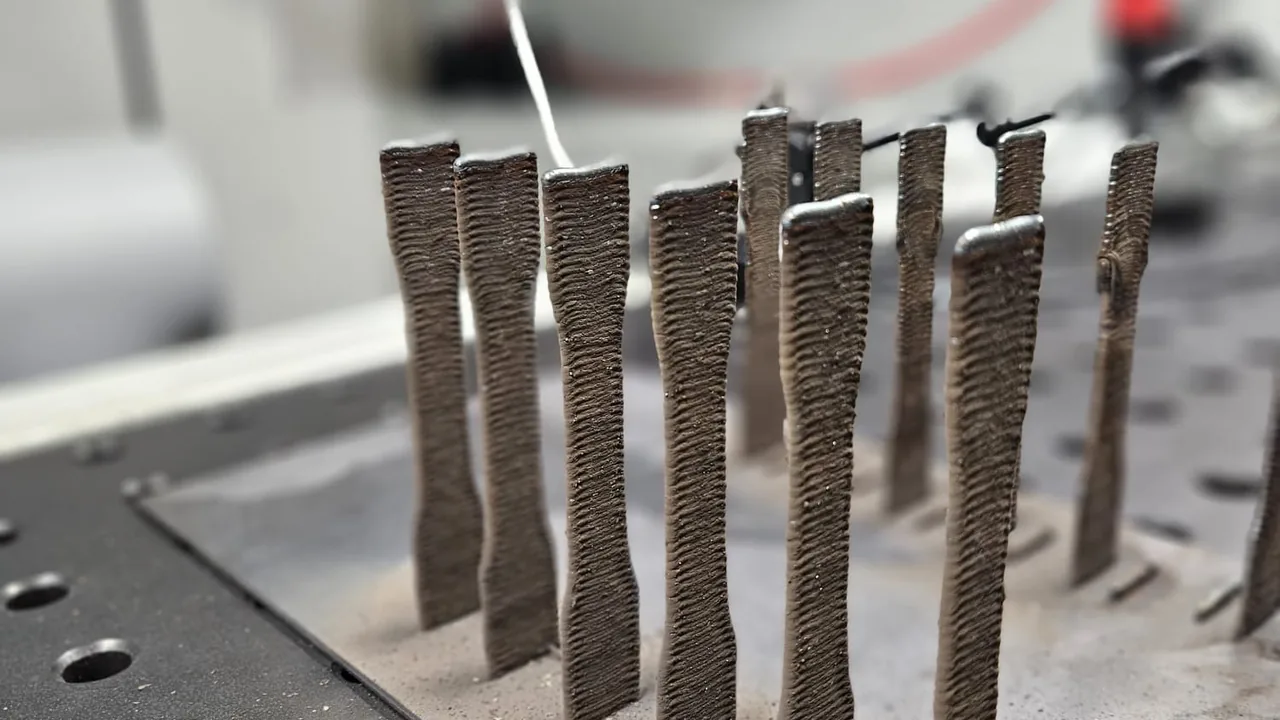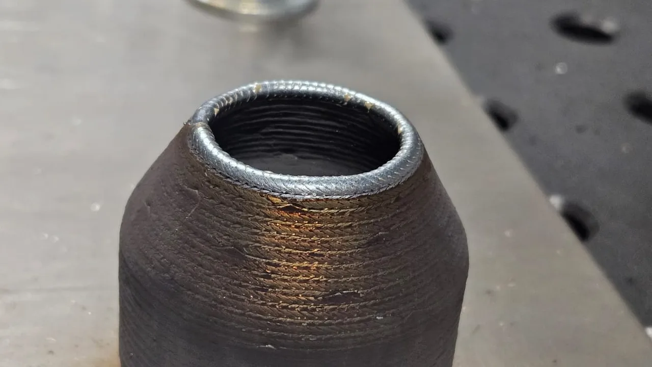
An oxide inclusion (ISO 6520-1 reference 303) is a fragment of the metal’s own surface oxide trapped inside the weld as it solidifies. It is most familiar on aluminium, whose oxide film forms almost instantly in air and melts at a far higher temperature than the base metal underneath, but the same mechanism affects other oxide-forming alloys.
This article is about what causes an oxide inclusion, why it is a process-control problem before it is an inspection problem, and what a real-time monitoring record can and cannot show about it. It does not set acceptance limits or replace the NDT method a contract requires.
Key takeaways
- Oxide inclusion is a solidification defect: a piece of surface oxide gets folded into the pool and cannot float out before freezing.
- On aluminium the driving cause is the mismatch between the oxide’s melting point and the base metal’s.
- Interpass cleaning, shielding gas coverage and, for AC TIG, cleaning-action balance are the process variables that control the risk.
- Continuous process monitoring can evidence whether those variables stayed in range pass to pass; it does not itself confirm the inclusion is absent.
- Final disposition still depends on the applicable NDT method and the project’s acceptance standard.
Why the oxide gets trapped
Aluminium forms a thin aluminium-oxide layer on any exposed surface within moments of contact with air. That oxide melts at a temperature far above the melting point of the aluminium beneath it, so during welding the oxide skin does not simply melt away with the parent metal — it has to be actively broken up and displaced, or it survives as a solid film inside a pool that is otherwise liquid.
If a fragment of that film folds into the weld pool as it advances and is not rejected to the surface before solidification reaches it, it freezes in place as an inclusion. The same logic applies, to varying degrees, to other alloys that carry a persistent oxide layer; the defects reference entry for oxide inclusion covers the ISO 6520-1 classification and related codes.
[Assumption / ipotesi] The relative weight of each contributing cause below depends on the process, alloy and joint design in use. Confirm the dominant cause on the target WPS before writing a corrective action.
What raises the risk
- Incomplete surface preparation. Filler wire or base metal that was not freshly brushed with a dedicated stainless-steel brush (never one shared with carbon steel) carries a heavier, less predictable oxide layer into the pool.
- Broken shielding gas coverage. Any gap in shielding — wind, an obstructed nozzle, excessive stick-out, travel speed too high for the gas flow — lets the surface reoxidize between the torch and full solidification.
- Insufficient AC cleaning action in GTAW. On aluminium, the cleaning half-cycle of an AC TIG waveform is what disrupts the oxide film ahead of the arc; a balance set too far toward penetration reduces that effect.
- Unremoved interpass oxide. In multi-pass work, an oxide layer that reforms on a cooling bead and is not brushed off before the next pass is deposited is carried straight into the new pool.
- Filler and base-metal storage. Wire or plate left unprotected, or handled with contaminated gloves, accumulates oxide and moisture-related surface film faster than stored material.
What a process record can show
An oxide inclusion itself does not have a distinctive thermal or electrical signature that a monitoring system reads directly — this is different from a defect like a slag inclusion, where interpass thermal behaviour is a closer proxy for the entrapment itself (see the companion article on slag inclusion). What a continuous record can do is document whether the process variables that control the risk stayed within the qualified range, pass by pass:
- Interpass surface preparation performed and timed against the WPS-required cleaning step.
- Shielding gas flow continuity through the pass, without unexplained drops.
- For AC GTAW, the cleaning/penetration balance and frequency actually delivered by the power source, against the qualified setting.
- Travel speed and stick-out within the window the WPS specifies for gas coverage.
That record answers “did the controls that prevent this defect operate as specified on this weld” — a narrower and more honest claim than “this weld has no oxide inclusion.” The welding monitoring system overview and HeatCore AI describe how thermal and process channels are combined into one evidence record per joint; for a fixed installation, HeatCam IR-C is the camera context.
[Assumption / ipotesi] Whether cleaning-action balance is available as a logged parameter depends on the power source and its data interface. Confirm this with the equipment vendor before writing it into the evidence plan.
Where detection still happens
Final confirmation of an oxide inclusion is an NDT question, not a process-monitoring one:
- Radiographic testing typically shows oxide inclusions as irregular indications, distinguishable in form from rounded gas porosity but not always easy to separate from other solid inclusions without a trained reader.
- Visual testing can catch a surface-breaking oxide film or a visibly dirty interpass surface before the next pass buries it — the same logic behind why weld defects tend to show up first in real-time infrared video: a process anomaly is often visible before it becomes a buried, sentenced defect.
- Ultrasonic testing is used on thicker sections, subject to the same reader qualification requirements as any other UT indication.
The applicable acceptance standard sets the limits that apply, by quality level and joint type. For aluminium and its alloys — the base material this article is about — that standard is ISO 10042, not ISO 5817: ISO 5817 covers fusion-welded joints in steel, nickel, titanium and their alloys and explicitly excludes aluminium. This article does not reproduce either standard’s limit tables; confirm the current edition, the correct standard for the base material in question, and the governing contract clause for the actual numbers.
Building the evidence pack
A defensible evidence record for an aluminium joint at risk of oxide inclusion links, at minimum: the WPS revision and its qualified cleaning and shielding parameters, the per-pass confirmation that those parameters were met, the operator or automated log of interpass cleaning, and the NDT result and disposition once inspection is complete. The every-weld coverage guide explains how to reconcile monitoring records against the full population of welds so a gap in the record is caught rather than silently assumed clean. For general aluminium process monitoring beyond this one defect, see aluminium welding quality monitoring with thermal imaging.
None of this replaces the inspection method the contract requires. The value of the process record is that it narrows the investigation when an inclusion is found — showing whether a specific pass, operator shift or equipment setting correlates with the finding — rather than leaving the next occurrence to be caught only at final RT.
Sources
- Therness oxide inclusion reference (ISO 6520-1, code 303) — classification and related defect codes.
- Slag inclusion in welding: causes, prevention — comparison with a related solid-inclusion defect.
- Therness welding monitoring system — system workflow and sensing context.
- Therness HeatCore AI — monitoring and analysis layer context.
- ISO 6520-1, Welding and allied processes — Classification of geometric imperfections in metallic materials — Part 1: Fusion welding — defect classification; verify the applicable edition.
- ISO 10042 — quality-level context for weld imperfections in aluminium and its alloys, the base material this article covers; check the governing contract clause and verify the current edition.
- ISO 5817 — the equivalent quality-level standard for steel, nickel and titanium alloys; it does not cover aluminium.
Confirm process control on aluminium welds
Therness can help define which shielding, cleaning and AC-balance parameters to log per pass, and how that record fits your NDT and disposition workflow.
Discuss your processTherness solution: Welding monitoring system — Every weld inspected in the cycle, with defect flags and the ISO 3834 / ISO 17635 evidence kept per weld.