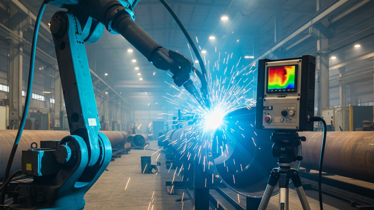
Real-time infrared video turns an invisible defect into a visible one, seconds before it exists
Real-time infrared video does not show you a finished weld — it shows you the joint while it is still being made, and that timing is the point. A thermal camera measures the infrared radiation leaving the surface and converts it to a temperature value, frame by frame, so what you are watching is a live map of where energy is going and how fast it is leaving. Three defect mechanisms — lack of fusion, burn-through, and an out-of-window cooling rate — each leave a distinct signature on that map before the weld has finished cooling, which is why this kind of monitoring catches problems that visual inspection and post-weld NDT cannot see until much later.
Key takeaways
- A thermal camera reads temperature from infrared radiation, not brightness — the picture is a physical measurement, not a photograph.
- Lack of fusion shows up as a cold spot: the parent metal did not get enough energy to melt and bond.
- Burn-through shows up as a hot spot with a widening, brightening pool before the metal opens.
- Cooling rate — the T8/5 interval — governs hardness and cracking risk in the heat-affected zone, and a camera can track it continuously.
- Emissivity has to be set for the real surface condition, not assumed, or the temperature reading is wrong by a predictable but unstated margin.
- None of this replaces the NDT method your specification requires; it tells you which welds are worth checking first.
- The useful measurement zone sits behind the arc, not on it — arc glare saturates the pixels closest to the source.
How a thermal camera turns heat into a defect signal
From photons to a temperature map
A visible camera records how much light a surface reflects. A thermal camera in the long-wave infrared band records how much a surface emits, and converts that flux to temperature using the Stefan–Boltzmann relationship between radiated power and temperature (reference on Wikipedia). That conversion depends on one more number: emissivity, the fraction of a perfect radiator’s output that the real surface actually produces. Get emissivity wrong and every temperature the camera reports is wrong by a consistent, silent offset — a documented failure mode covered in more depth by the NDE-ED introduction to thermal testing science. Oxidized steel, bare aluminium, and a freshly ground weld cap all have different emissivities, and none of them match a generic default.
Why brightness is not temperature
This detail trips up anyone reading thermal footage like a normal video. A pixel that looks “brighter” in a false-colour palette is not automatically hotter in an absolute sense — the palette is scaled to the frame’s own temperature range, so the same colour can mean different things in two different clips. What is comparable, frame to frame and pass to pass, is the calibrated temperature value behind each pixel, which is why production systems log the numbers rather than the picture alone.
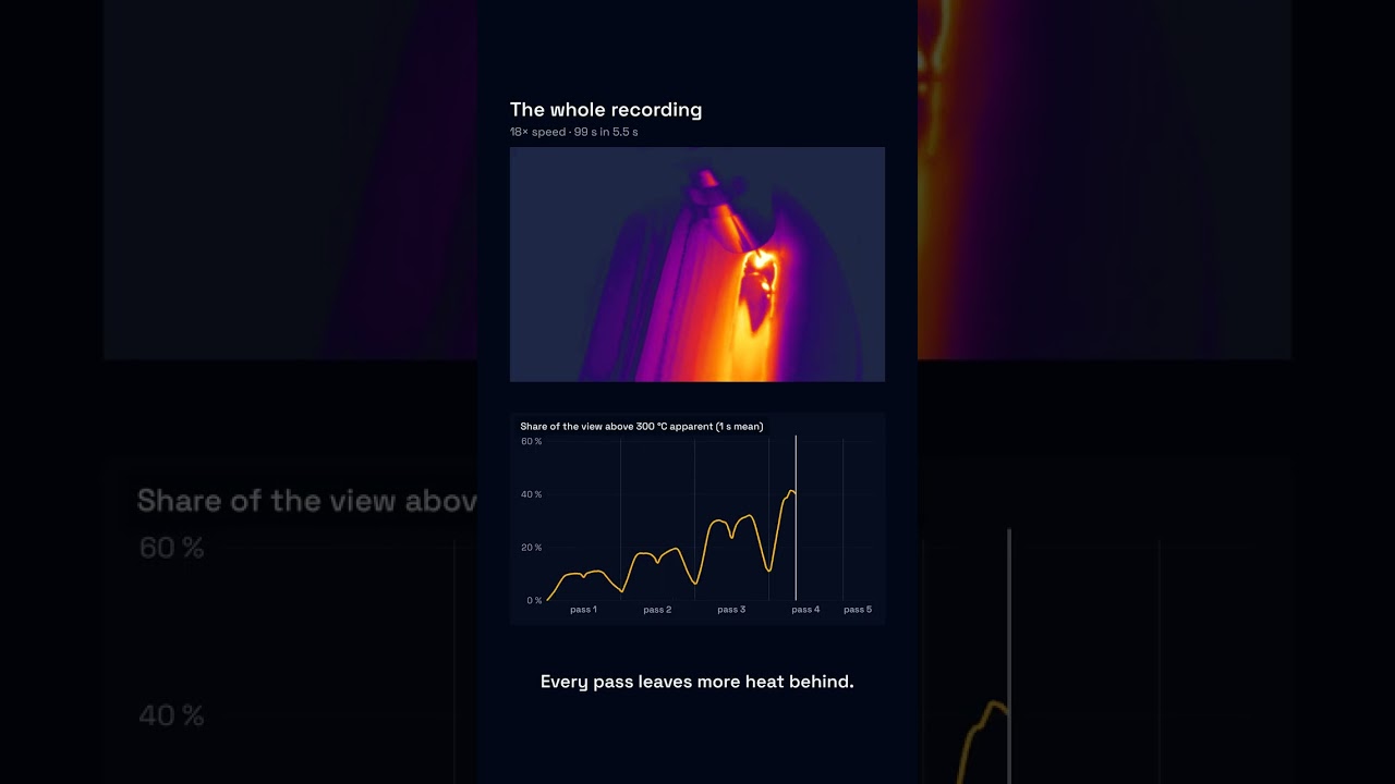
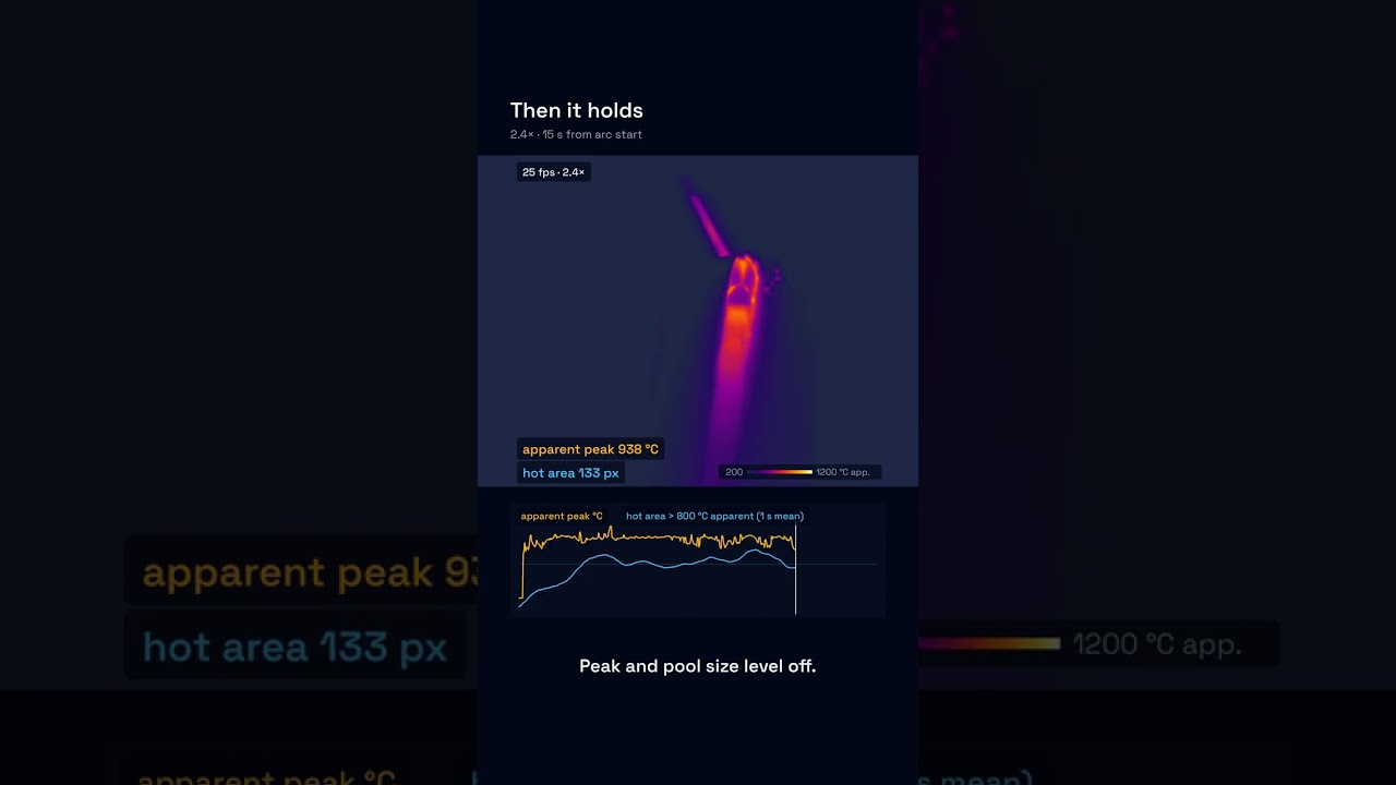
The clip above comes from the Therness R&D robot cell: a wire arc additive manufacturing (WAAM) wall filmed by a thermal camera mounted on the torch at 25 frames per second, five passes in 99 seconds. Watch the wall behind the torch rather than the arc: the heat stays in the part long after the torch has moved on, and that slow fade is the cooling behaviour the rest of this article is about. The clip at the top of the page shows a single robotic cladding pass from the same kind of torch-mounted camera, with the temperature scale in apparent °C; the real-time thermal imaging in welding page walks through it.
The defect signatures that appear while the arc is still moving
Lack of fusion — the cold-spot mechanism
Lack of fusion is ISO 6520-1 reference 401: the weld metal did not fuse to the base metal or to a previous pass. Thermally, it is starvation, not excess — not enough energy reached that point to bring the parent surface to melting temperature, so it stays cooler than the surrounding bead and shows as a localized cold region relative to the rest of the pool. It tends to appear at a joint edge, a root, or a pass boundary rather than in open plate, and it repeats at the same relative position when a fixture, a joint fit-up gap, or a travel-speed spike is the underlying cause. Cross-reference it against the glossary entry on lack of fusion and the defect reference page for ISO 6520-1 code 401 for the fuller cause matrix.
Burn-through — the energy-pileup mechanism
Burn-through is the opposite failure: too much energy arriving too fast for the joint to carry away, so the pool widens, deepens, and eventually opens a hole. In infrared it announces itself before it happens — the pool brightens and widens over several consecutive frames as heat piles up faster than it can conduct into the surrounding mass — the warning window a real-time system is built to catch. See the defect reference for burn-through for the underlying cause matrix.
Slow cooling drift — heat-affected-zone risk
The third signature is not a spot at all but a trend: the rate at which each point on the bead cools once the arc has moved on. This is the cooling curve — commonly tracked as the T8/5 interval, the time to fall from 800°C to 500°C — and it governs the microstructure that forms in the heat-affected zone. Cool too fast and hardness and cracking risk rise; cool too slowly and toughness can suffer along with productivity. Because the camera measures this continuously, a drift in travel speed, preheat, or interpass temperature shows up as a shift in the cooling curve long before a coupon would ever be cut to check it — the full mechanics of that relationship are in our guide to heat input and T8/5 cooling rate.
The three signatures share one property: they are all visible in the temperature field, not the visible-light image. That is the argument for putting a thermal camera on a joint that already has a visual weld camera — the two answer different questions. See the comparison in welding camera vs. thermal camera.
Setting up a system to catch this live: step by step
- Fix the field of view. Frame the pool, the trailing bead, and a margin of the heat-affected zone — not the arc, which saturates the sensor with glare and carries no usable temperature data there.
- Calibrate emissivity against the real surface. Take a reference reading with a contact thermocouple or a known high-emissivity reference patch on the actual material and surface finish being welded, not a generic table value. Repeat whenever material, surface prep, or a protective window changes — see the Engineering Toolbox emissivity reference table for how widely emissivity varies by surface condition alone.
- Set the sampling rate to the travel speed. The camera has to resolve the region of interest moving through the frame without gaps large enough to hide a transient event — faster travel speed and a tighter zoom both push the required frame rate up.
- Define the baseline. Run a known-good procedure and record peak temperature, cooling rate, and heat-affected-zone width as the reference band for that joint and material combination. Without a baseline, “unusual” has no meaning.
- Set thresholds, not a single pass/fail line. A cold-spot threshold, a hot-spot threshold, and a cooling-rate window each need their own tolerance, because they represent different failure physics and drift independently.
- Route the alert. Decide what happens when a threshold trips — an operator prompt, a weld-log flag for later NDT prioritization, or a hard stop — before the system goes live, not after the first false alarm.
- Log the data, not just the alarm. A continuous temperature record per weld is what lets you correlate a later NDT finding back to the exact frame that produced it.
A real-time weld monitoring system built around a thermal camera such as HeatCam IR-C or the more compact HeatCam IR-S for tighter robotic cells carries out these steps as a standing configuration rather than a one-off calibration exercise.
Failure modes and fixes
| Symptom | Likely cause | Fix |
|---|---|---|
| Every weld reads “hot,” even good ones | Emissivity set too low for the surface | Recalibrate against a contact reference on the real surface condition |
| Frequent short spikes that don’t repeat | Spatter droplets or reflections crossing the field of view | Filter on multi-frame persistence before flagging a defect |
| Cold-spot alarms only near clamps or fixtures | Reflected background temperature, not the part itself | Move or shield the fixture, or correct for reflected apparent temperature |
| Same joint reads differently machine to machine | No shared baseline between cells | Record a reference pass per material/process combination on every cell |
| Real defect confirmed by NDT, but the camera never alarmed | Threshold set from a single “typical” run, not a real spread | Rebuild thresholds from a wider sample including edge-case good welds |
| Signal looks fine but the part still failed testing | Camera view did not include the actual defect location (root pass, second side) | Reframe or add a second camera for passes the first view cannot see |
Verifying the read: proving live infrared against ground truth
A real-time thermal signal is only as trustworthy as the last time it was checked against something independent. That check has two layers.
Correlating with destructive and NDT results
During procedure qualification, and again whenever material, wire, gas, or preheat changes, pull the coupon and compare what the camera logged for that exact weld against the metallurgical or NDT finding. A cold-spot alarm that lines up with a confirmed lack-of-fusion indication earns trust; one that never correlates with anything real is a threshold problem, not a monitoring success. ISO 6520-1 gives the common vocabulary for naming what the destructive test finds, and ISO 17635 lays out the general rules for choosing which NDT method actually confirms it.
Documenting the evidence chain
An auditor asks for the pairing, not the claim: the thermal record, the threshold it was checked against, and the confirming test where one was run. Keep emissivity settings, the calibration date, and the field of view alongside it — a value with no context is just a number. AWS D1.1 and equivalent structural codes describe the acceptance route the confirmation has to satisfy; the thermal record supports that route, it does not substitute for it.
When to trust the live read versus when to send it for confirmation
| Situation | Real-time infrared is enough to | Still send to NDT/destructive test |
|---|---|---|
| Routine production pass within the established baseline band | Confirm the process ran inside its normal window | No — normal sampling plan still applies |
| A single frame shows a transient spike with no persistence | Log it and move on | Only if it recurs or correlates with other data |
| A cold spot repeats at the same joint location across multiple parts | Flag the joint for priority inspection | Yes — before the part ships |
| Cooling rate drifts outside the reference band for several consecutive welds | Stop and check preheat/interpass practice | Yes, on any part welded during the drift |
| First article or procedure qualification | Provide the thermal record as supporting evidence | Always — qualification requires the specified test regardless |
A general reference on interpreting infrared imagery for defect indications, independent of any single vendor, is the NDE-ED chapter on image interpretation.
Where this fits alongside other inspection routes
Real-time infrared is a process signal, not a replacement for the acceptance testing a specification requires. It earns its place by telling you which welds deserve that testing first, and by giving a continuous record for the ones that pass. A certified NDT technician still signs off the confirming test; the alarm only routes work to them faster. Camera operators need the same basic welding hazard awareness as anyone near the arc — see OSHA’s welding, cutting and brazing topic page — and a broader look at where thermal evidence fits an inspection plan is in our guide to thermography as NDT evidence. For the complete setup-to-standards walkthrough covering the same video, see infrared thermography for welding: real-time quality.
FAQ
How fast does a thermal camera need to sample to catch a moving weld defect? Fast enough that the region of interest does not move more than a fraction of its own size between frames. At typical arc travel speeds that means tens of frames per second for a wide field of view, and higher still for a tight zoom on the pool itself.
Can real-time infrared video replace radiographic testing after the weld cools? No. It is a process signal that flags risk while the arc is moving, not a volumetric acceptance test. A confirmed cold spot or hot spot still routes to the NDT method the applicable standard actually calls for.
Why does a cold spot in infrared video mean lack of fusion rather than a camera glitch? Because it appears at the same location relative to the bead on every pass, tracks with travel speed, and correlates with a parameter dip (voltage sag, wire feed hesitation). A sensor glitch is a single frame with no spatial or parameter correlation.
Does surface spatter cause false defect readings in live infrared weld video? Yes, briefly. A spatter droplet reads as a small, short-lived hot pixel that does not persist or move with the pool, unlike a real hot spot from energy pileup. Filtering on persistence across several frames removes most of it.
What frame rate is enough to see a burn-through forming before it breaks through? The onset shows as a widening, brightening pool over several consecutive frames before the metal actually opens up, so a camera sampling in the tens of frames per second at the joint gives two or three frames of warning at normal travel speeds.
How is emissivity set for real-time infrared weld video on different base metals? Against a reference measurement — a thermocouple or a known high-emissivity patch — taken on the actual surface condition being welded, not a textbook value. Oxidized steel, bare aluminium and a ground weld cap all radiate differently and need their own check.
Can real-time infrared video catch defects that visual inspection would miss? It flags surface signatures consistent with sub-surface lack of fusion, a cooling rate outside the target window, or a slow parameter drift — patterns visual inspection cannot see at all. It cannot see a crack that opens after the frame has cooled and moved on.
What happens to the infrared signal when arc glare saturates the sensor? The pixels nearest the arc clip to the camera’s maximum reading and stop carrying temperature information, which is why the useful measurement zone sits a short distance behind the arc, in the pool and the trailing bead, not on the arc itself.
See this running on your own joint
Tell us the material, the joint type and where lack of fusion or burn-through has cost you rework. We will show what a real-time thermal record looks like on your process.
Talk to us about real-time thermal monitoringTherness solution: Welding camera — Thermal and high-speed imaging that watches the arc, the pool and the cooling seam while the weld is made.
Frequently Asked Questions
How fast does a thermal camera need to sample to catch a moving weld defect?
Fast enough that the region of interest does not move more than a fraction of its own size between frames. At typical arc travel speeds that means tens of frames per second for a wide field of view, and higher still for a tight zoom on the pool itself.
Can real-time infrared video replace radiographic testing after the weld cools?
No. It is a process signal that flags risk while the arc is moving, not a volumetric acceptance test. A confirmed cold spot or hot spot still routes to the NDT method the applicable standard actually calls for.
Why does a cold spot in infrared video mean lack of fusion rather than a camera glitch?
Because it appears at the same location relative to the bead on every pass, tracks with travel speed, and correlates with a parameter dip (voltage sag, wire feed hesitation). A sensor glitch is a single frame with no spatial or parameter correlation.
Does surface spatter cause false defect readings in live infrared weld video?
Yes, briefly. A spatter droplet reads as a small, short-lived hot pixel that does not persist or move with the pool, unlike a real hot spot from energy pileup. Filtering on persistence across several frames removes most of it.
What frame rate is enough to see a burn-through forming before it breaks through?
The onset shows as a widening, brightening pool over several consecutive frames before the metal actually opens up, so a camera sampling in the tens of frames per second at the joint gives two or three frames of warning at normal travel speeds.
How is emissivity set for real-time infrared weld video on different base metals?
Against a reference measurement — a thermocouple or a known high-emissivity patch — taken on the actual surface condition being welded, not a textbook value. Oxidized steel, bare aluminium and a ground weld cap all radiate differently and need their own check.
Can real-time infrared video catch defects that visual inspection would miss?
It flags surface signatures consistent with sub-surface lack of fusion, a cooling rate outside the target window, or a slow parameter drift — patterns visual inspection cannot see at all. It cannot see a crack that opens after the frame has cooled and moved on.
What happens to the infrared signal when arc glare saturates the sensor?
The pixels nearest the arc clip to the camera's maximum reading and stop carrying temperature information, which is why the useful measurement zone sits a short distance behind the arc, in the pool and the trailing bead, not on the arc itself.
Related Video