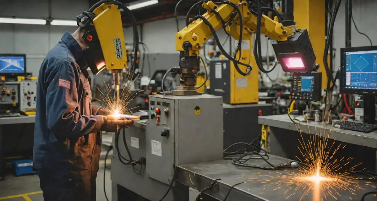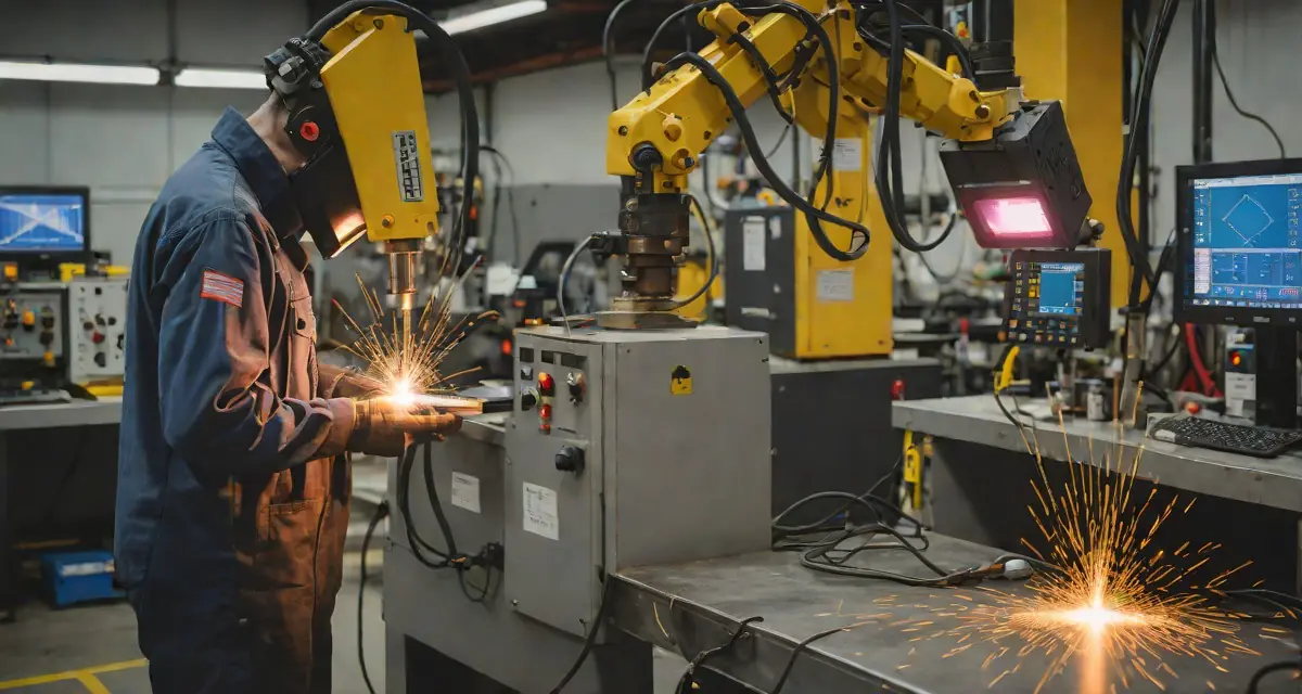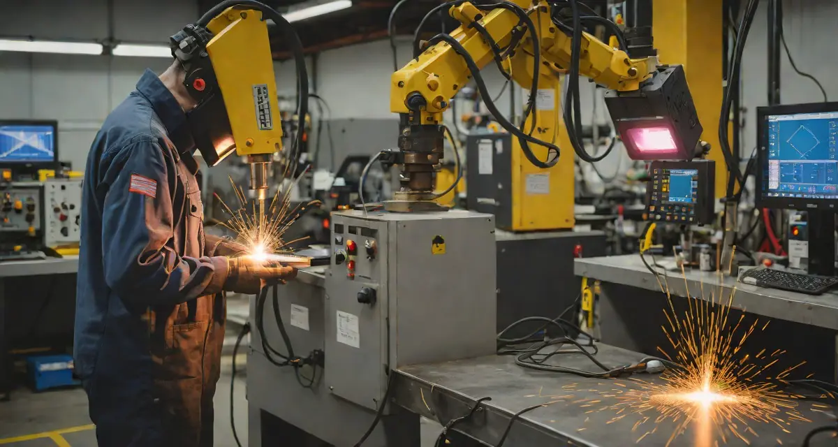
TIG welding quality monitoring is a critical challenge for manufacturers in aerospace, nuclear, pharmaceutical piping, and food & beverage processing — industries where incomplete penetration or porosity in a single weld can trigger catastrophic failure, regulatory non-compliance, or costly full-line teardowns.
Tungsten Inert Gas (TIG) welding, formally known as Gas Tungsten Arc Welding (GTAW), produces some of the highest-quality welds in manufacturing. But that quality comes with complexity: tight heat input windows, sensitivity to contamination, and defects that are often invisible to the naked eye until post-weld inspection reveals them — when it’s already too late.
Real-time thermal imaging changes this equation. By capturing the weld pool’s thermal signature at every arc-on moment, TIG welding quality monitoring systems catch defects at formation — not after they’re buried in a pipe wall or structural joint.
Why TIG/GTAW Welding Demands Dedicated Quality Monitoring
TIG welding is the process of choice when precision matters most:
- Aerospace structures and engine components — titanium and nickel superalloy weldments where any porosity or lack of fusion can propagate fatigue cracks under cyclic load
- Pharmaceutical and food-grade piping — stainless steel orbital TIG welds subject to crevice corrosion if penetration is incomplete, and biofilm entrapment if the weld bead profile is irregular
- Nuclear pressure boundary components — ASME Section III and ASME Section IX Procedure Qualification Records (PQRs) demand full traceability of every weld parameter
- High-purity semiconductor and chemical process piping — autogenous orbital TIG with zero filler, where heat input variation of even a few joules per millimeter can shift bead geometry outside spec
Despite these demanding applications, the quality monitoring toolset at most shops still relies on:
- Post-weld visual inspection (catches surface defects only)
- Radiographic or ultrasonic testing (offline, sampled, slow)
- Welder manual log sheets (human error, no real-time feedback)
This is a significant gap. And it’s exactly what inline in-process weld monitoring of the GTAW arc closes.
Common GTAW Defects Detectable with Thermal Imaging
Thermal imaging detects defects by their thermal signature — the distinctive temperature anomalies that form at the weld pool boundary when heat transfer deviates from the expected process envelope.
The most economically impactful GTAW defects — and their thermal signatures — include:
1. Incomplete Root Penetration
The most critical defect in pipe welding. When welding current is too low, travel speed too high, or joint gap insufficient, the root pass fails to fuse fully through the base material thickness.
Thermal signature: The root-side thermal isotherm narrows and asymmetry appears in the cross-weld temperature gradient. In orbital TIG monitoring, this manifests as a drop in the centroid temperature of the weld pool rear boundary below process threshold.
2. Burn-Through (Excessive Penetration)
The inverse problem — too much heat input on thin-wall or open-root joints collapses the molten pool through the root, creating a depression or hole.
Thermal signature: Rapid temperature spike in the penetration zone combined with pool width expansion beyond the ±2σ control limit. Detectable in real time, enabling arc-off or current ramp-down before the joint is destroyed.
3. Tungsten Inclusion
When the tungsten electrode contacts the weld pool or is contaminated, fragments embed in the weld metal. Tungsten inclusions are dense, highly visible on X-ray, and cause weld rejection in aerospace PQR review.
Thermal signature: Point-source temperature spike at contact event; pool disturbance in the immediately following frames. Can be flagged as a discrete event within 50–100 ms of occurrence.
4. Porosity
Gas entrapment — from surface contamination, shielding gas disruption, or moisture in the joint — creates voids that reduce cross-sectional weld area and act as fatigue crack initiation sites.
Thermal signature: Micro-voids manifest as localised cold spots as trapped gas conducts heat differently from the surrounding solidified metal. AI-assisted thermal analysis can distinguish porosity-related cold spot patterns from normal solidification variation.
5. Hot Cracking (Solidification Cracking)
Common in austenitic stainless steel and some nickel alloys, solidification cracking occurs when low-melting-point liquid films along grain boundaries cannot sustain the tensile stress during weld metal contraction.
Thermal signature: Anomalous cooling rate in the solidification tail — slower than expected (indicating liquid film persistence) followed by rapid cooling discontinuity. The characteristic Δt 8/5 cooling rate signature deviates from the process-specific baseline.
The Physics Behind Thermal Monitoring of TIG Welds
Every welding defect is a heat transfer anomaly. Thermal imaging makes those anomalies visible in real time.
TIG welding involves the most concentrated, stable arc of any fusion process — which makes it ideally suited for thermal monitoring (watch real-time thermal imaging of a live weld). The heat input is controllable, repeatable, and directly correlated to weld pool geometry.
ISO 4063 designates GTAW as Process 141 (with filler) and 142 (autogenous). In both variants, the thermal monitoring model is the same:
Monitored thermal parameters:
- Peak weld pool temperature — proxy for heat input compliance
- Weld pool area and aspect ratio — correlates with penetration depth and bead width
- Thermal gradient (front vs. rear boundary) — indicates travel speed and heat dissipation
- Solidification tail length and cooling rate — predicts HAZ microstructure and cracking susceptibility
- Inter-pass temperature — critical for multi-pass TIG on stainless steel (sensitization prevention) per ISO 13916
For orbital TIG monitoring on pipe, the model adds:
- Angular position correlation — maps thermal anomalies to weld clock positions (12 o’clock, 3 o’clock, etc.) for targeted repair instructions
- Wall thickness compensation — adjusts the baseline model as pipe geometry creates variable heat sink effects around the circumference
Inline TIG Welding Quality Monitoring: System Architecture
A production-ready TIG welding quality monitoring system for GTAW consists of three integrated layers:
Layer 1: Thermal Sensing
Short-wave infrared (SWIR) or mid-wave infrared (MWIR) thermal cameras mounted at fixed geometry relative to the torch. For orbital TIG, the camera rotates with the weld head on the orbital carriage, maintaining constant standoff and viewing angle throughout the 360° rotation.
Critical specifications:
- Frame rate: ≥ 100 Hz (to resolve the ~10 ms thermal transients in fast TIG arcs)
- Spatial resolution: < 0.5 mm/pixel at the weld pool scale
- Dynamic range: sufficient to avoid saturation on the arc peak while resolving pool boundary isotherms
- Shielding gas compatibility: camera purge or optical filter to prevent lens contamination in inert gas environments
Layer 2: AI-Based Process Analysis
Real-time signal processing — the job of HeatCore AI in GTAW cells — converts the raw thermal data stream into process quality indicators:
- Pool segmentation — separates the weld pool from arc and surrounding material
- Feature extraction — computes pool area, centroid, gradients, and isotherm positions per frame
- Anomaly detection — compares live features against the qualified process envelope (established during ISO 15614 WPQR qualification)
- Defect classification — assigns detected anomalies to defect categories with confidence scores
This is the same analytical approach used in sensor fusion weld quality monitoring systems — thermal data can be complemented with acoustic emission or optical arc monitoring for higher classification accuracy.
Layer 3: Traceability and QMS Integration
Every weld’s thermal profile is timestamped, linked to the WPS/PQR, welder ID, and joint ID, and stored in the weld quality database. This enables:
- Digital welder qualification tracking against certified process windows
- ISO 3834 welding quality records with full parameter traceability
- ASME Section IX documentation for pressure-boundary welds
- Automatic NCR generation when anomalies exceed acceptance thresholds, routed through the welding NCR management workflow
GTAW Applications: Industry-by-Industry
Aerospace and Defense
Titanium, Inconel, and aluminum alloy weldments in airframes, engine components, and spacecraft structures demand zero-defect production. Post-weld NDT (X-ray, PAUT) remains mandatory, but inline thermal monitoring dramatically reduces the failure-to-inspect ratio.
Thermal monitoring catches burn-through and tungsten inclusion events within 100 ms, enabling immediate arc interrupt before the defect propagates further along the joint.
Pharmaceutical and Food-Grade Piping
Orbital TIG on sanitary stainless steel piping (316L, 304L) is governed by ASME BPE (Bioprocessing Equipment) standards for weld bead geometry and surface finish. Incomplete root penetration creates entrapment zones that cannot be cleaned — a direct GMP (Good Manufacturing Practice) violation.
Inline thermal monitoring of orbital TIG provides:
- Root penetration confirmation on every joint (not sampled inspection)
- Automatic documentation for FDA validation packages (IQ/OQ/PQ)
- Immediate reject flagging with joint ID and clock position for targeted borescope inspection
Nuclear and Power Generation
ASME Section III Class 1, 2, and 3 weldments require 100% NDE and full parameter documentation. Thermal monitoring complements but does not replace mandatory NDE — instead, it provides continuous process surveillance that catches out-of-spec conditions before they become rejectable welds.
Integration with the welding data historian maintains the immutable parameter record required for nuclear quality assurance (QA Level 1).
Stainless Steel Fabrication
For multi-pass TIG on austenitic stainless steel, interpass temperature control is critical. Temperatures above 150°C inter-pass can cause sensitization — chromium carbide precipitation at grain boundaries — which dramatically reduces corrosion resistance.
Real-time interpass temperature monitoring per welding preheat and interpass temperature ISO 13916 methodology prevents sensitization and eliminates the need for post-weld annealing in most applications.
Qualifying the TIG Monitoring Process: Integration with WPS and PQR
The thermal monitoring system must be qualified as part of the Welding Procedure Specification (WPS), not added as an afterthought. The process envelope used for anomaly detection is derived from qualification welds, not from generic literature values.
The qualification workflow for TIG welding quality monitoring:
- Establish baseline: Run 10–20 qualification welds under controlled conditions at the WPS limits. Record the thermal profile for each weld that passes full NDE.
- Define process envelope: Statistical analysis of the baseline set defines the ±3σ control limits for each monitored thermal feature.
- Validate detection sensitivity: Intentionally introduce known defects (reduced current for incomplete penetration, contamination for porosity) and confirm the monitoring system detects each defect type with the required sensitivity.
- Document in PQR: The thermal monitoring system model, camera specification, and control limits become part of the ISO 15614 Procedure Qualification Record.
- Production deployment: The qualified process envelope is deployed to the production monitoring system. Any weld that generates an anomaly flag is diverted to targeted NDE rather than routine sampling.
This approach — qualifying the monitoring system alongside the welding procedure — is aligned with ISO 17662 requirements for calibration, verification, and validation of monitoring and measuring equipment used in welding.
ROI: What TIG Welding Quality Monitoring Delivers
The economic case for inline TIG monitoring is straightforward in high-value applications:
Cost of post-weld rejection (aerospace pipe weld, 12” diameter, 1 pass):
- Radiographic inspection: €80–150
- Repair excavation and re-weld: €400–800
- Post-repair NDE: €80–150
- Documentation and NCR processing: €100–200
- Total per rejected weld: €660–1,300
Cost of inline thermal monitoring catch (same weld):
- Arc interrupt within 100 ms of defect detection
- Repair confined to defect zone (not full weld re-run)
- Single targeted borescope or X-ray shot
- Total per caught defect: €80–200
At a rejection rate of even 0.5% on a 500-weld/month aerospace piping programme, inline monitoring pays for itself in under 12 months — and that calculation excludes the schedule risk of late NDE rejections.
For a structured ROI analysis for your specific application, use the welding quality ROI calculator.
Getting Started: Implementing TIG Welding Quality Monitoring
The implementation path for TIG/GTAW inline monitoring follows the same framework as other process monitoring deployments — detailed in the AI weld monitoring implementation guide:
- Process audit: Document current WPS, typical defect modes, post-weld NDE scope, and rejection rates
- Camera selection and mounting design: Choose SWIR/MWIR sensor, frame rate, and resolution for your specific joint geometry and access constraints — browse our monitoring products for the camera options
- Qualification weld programme: Generate the baseline thermal dataset under certified welding engineer supervision
- Software configuration: Define the process envelope, alert thresholds, and integration with your QMS
- Production trial: Run parallel monitoring (inline + full NDE) to validate detection performance before transitioning to targeted NDE
- Full deployment: Inline monitoring becomes the primary quality gate; NDE is triggered by monitor alerts and periodic audits
Ready to Monitor Your TIG/GTAW Lines in Real Time?
HeatCore integrates with orbital and manual TIG welding cells across aerospace, pharmaceutical piping, and precision fabrication. Book a technical demo to see live weld pool analysis on your process.
Book a TIG Monitoring DemoSummary
TIG welding quality monitoring with real-time thermal imaging closes the gap between WPS intent and production reality. For industries where weld integrity is non-negotiable — aerospace, nuclear, pharmaceutical piping, precision fabrication — it transforms quality assurance from a post-production cost centre into an inline, data-driven process control system.
Key takeaways:
- Defects detected inline: incomplete penetration, burn-through, tungsten inclusion, porosity, hot cracking
- Detection latency: < 100 ms for discrete events; continuous process envelope monitoring for gradual drift
- Integration: WPS/PQR, ISO 3834, ASME Section IX, FDA validation documentation
- ROI: Positive in < 12 months in high-value, high-rejection-risk applications
The data from every TIG weld becomes a quality record, a process improvement input, and an audit trail — automatically.
Therness solution: Welding camera — Thermal and high-speed imaging that watches the arc, the pool and the cooling seam while the weld is made.