Building a near-net-shape feature with wire-arc additive manufacturing (WAAM) is not the same problem as building a wall. A gear tooth is short, tapered, and asymmetric — three properties that work against the thing that keeps a WAAM build stable: somewhere for accumulated heat to go. Path planning has to place each bead so the taper closes cleanly, the overhang at the root has to be carried by a pool that has not yet solidified, and the sequence has to stay inside a thermal window narrow enough that the profile does not slump before it cools. Get any one wrong and the defect shows up as a bulged flank, a cold layer, or both on the same tooth.
This article walks through those three constraints in the order a build meets them, and where in-process monitoring earns its place — not an inspection step at the end, but the way each layer is proved good before the next one lands on top of it.
Key takeaways
- A gear tooth’s short, tapered, asymmetric profile removes the heat escape a tall uniform wall has, so wall limits do not transfer directly.
- Path planning decides bead placement layer by layer, including where the toolpath reverses so heat does not stack at one end.
- Overhang appears at specific transitions — the root fillet, a bead’s own edge past its contact patch — not across the whole profile.
- Interpass temperature ties path planning and overhang together: too hot and an overhang sags, too cold and fusion weakens.
- A layer that ran outside the window is buried within minutes, so verification has to happen per layer, not only at the end.
- No standard specifies the toolpath or overhang limit for a feature — those are process-development decisions proven on your own equipment.
Watching the deposition up close

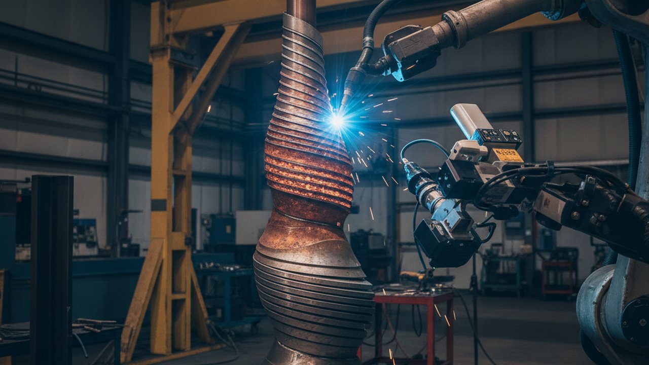
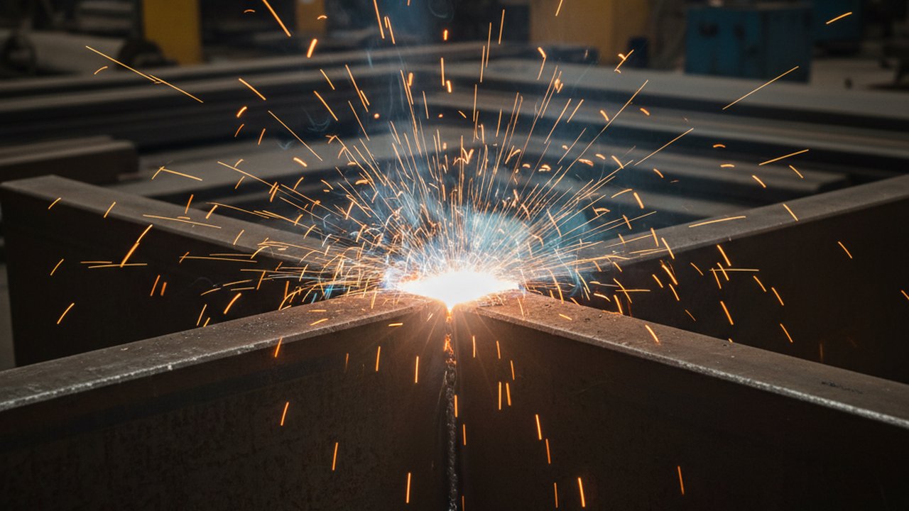
In the clip, the arc melts incoming wire into a small pool that has to solidify enough to support the next bead while fusing fully to the layer beneath it. A gear tooth makes both harder than a straight wall, because the profile is asymmetric and narrows toward its tip — a useful shape for studying path planning, overhang, and thermal limits together.
Path planning for a tapered, asymmetric profile
On a uniform wall, path planning is close to repetitive: the same bead, offset the same amount, layer after layer. A tapered profile removes that shortcut: each layer’s toolpath has to step in from the one below it, and the two flanks of an asymmetric tooth do not narrow at the same rate, so a single symmetric offset strategy gets one side wrong.
Two decisions carry most of the consequence:
- Where the toolpath starts and reverses. A short bead always starting and stopping at the same end stacks heat there, pass after pass. Alternating the start point spreads it instead.
- How aggressively each layer steps in as the taper closes. A large step-in keeps deposition fast but leaves less material at the width the next layer needs — and it is at the root, where the fillet flares back out toward the blank, that a step in the wrong direction turns into real overhang.
Neither has a universal answer: it depends on alloy, bead geometry, and machining stock. What generalises is the failure mode — a path planned for a wall, applied unchanged to a tapered feature, concentrates heat where the geometry can least afford it.
Overhang: what is actually holding the pool up
Overhang is any region of a new layer that does not sit directly on a fully solidified layer beneath it — support comes mainly from surface tension resisting gravity rather than a solid surface underneath. Built root to tip with each layer stepping in, most of a tooth’s profile has full support: a narrower layer sitting inside the footprint of the wider one below it. Overhang still shows up where the geometry breaks that pattern — at the root fillet, where the profile flares back out toward the blank instead of continuing to narrow, and along the outer edge of every bead, whose solidified cross-section is typically a little wider than the toolpath offset that placed it.
A pool under overhang has less margin before it fails. Push more heat into it — from travel speed, wire feed rate, or residual heat the previous layer had not shed — and the balance tips toward sag: the underside bulges, showing up as a visibly out-of-profile flank rather than a defect buried inside a thick wall.
How much overhang a given alloy, bead size, and interpass condition can carry is a question to establish empirically on your own equipment, not a number worth quoting in the abstract — the honest framing is an estimate bounded by those three variables, never a fixed angle claimed to apply generally.
Overhang tolerance and toolpath strategy are process-development decisions proven on the equipment actually running the build. AWS D20.1 governs qualification of the procedure, machine, and operator, and the NDT acceptance criteria applied afterward — it does not specify a toolpath or an overhang limit for a given feature, and this article does not either.
Thermal limits: the window that ties it together
Interpass temperature — the temperature of the deposit immediately before the next layer starts — connects path planning and overhang into a single constraint. Hold each new layer within the window qualified for the alloy, and the geometry stays true. Drift above it, on an overhang region already close to its limit, and the pool has less resistance before it sags. Drift below it, and the new bead can fuse poorly to the layer beneath — a lack-of-fusion condition (ISO 6520-1 reference 401) the geometry alone will not show.
The interpass temperature glossary entry covers where that measurement is taken; why the window narrows as heat accumulates is covered in why carbon steel WAAM walls slump and WAAM interlayer temperature control. A gear tooth does not change that physics — it shrinks the margin before an excursion is visible.
How monitoring proves each layer before the next one lands
The problem with these failure modes is timing: a layer that ran hot or cold is covered within minutes, and by the time the part reaches the inspection bench, the evidence for which layer went wrong is gone. Proving a layer good has to happen while it is still the top layer:
- Thermal imaging tracks the full layer, not a single fixed point, so a hot spot on one flank of an asymmetric tooth shows up even when the average looks fine.
- A recorded interpass reading per layer turns “the build finished” into a record of exactly where, if anywhere, the window was exceeded.
- Flagging drift while the build runs lets an operator correct dwell time or travel speed before the next layer deposits, not only after the part is off the machine.
HeatCam IR-S is built for close-range thermal reading on WAAM and other compact deposition setups; HeatCore AI scores that trend layer by layer and raises the flag while the build runs. Neither replaces a qualified procedure — they give the person running it evidence it was followed.
Failure modes and fixes
- Toolpath copied from a wall build without adjusting for the taper. Heat concentrates at one end. Fix: plan start point and step-in for the profile, alternating direction where possible.
- Overhang tolerance assumed rather than measured for the alloy in use. A flank sags on a build that looked fine with a different material or bead size. Fix: establish the limit for the actual alloy and interpass condition first.
- Interpass temperature checked at one point, not across the layer. A hot spot on one flank is missed as the average reads fine. Fix: use thermal imaging across the full layer.
- Verification happens only after the part is finished. The layer that caused a sagged flank or lack-of-fusion can no longer be corrected. Fix: record interpass temperature per layer while the build runs.
- The machining allowance is not planned into the near-net-shape target. The deposit ends up too close to final, or too far off. Fix: set the target with the allowance in mind from layer one.
Step-by-step: planning and verifying a near-net-shape feature build
- Model the taper as a sequence of layer offsets, not a single average profile, so each layer’s step-in is a deliberate choice rather than a fixed default.
- Identify where overhang occurs on the profile — on a gear tooth, at the root fillet and along every bead’s outer edge — and note which regions carry the least support.
- Establish the interpass temperature window for the alloy and bead size on a trial build, before committing the production toolpath.
- Instrument the build with thermal imaging that reads across the full layer, so an off-window reading on one flank is visible even when the average looks fine.
- Record interpass temperature per layer as part of the build record, so an out-of-profile flank can be traced back to the layer and condition that caused it.
From a video to a repeatable process
Watching the arc and the melt pool on a short clip is a useful way to see how path planning, overhang, and thermal limits interact on one feature. Turning that into a repeatable process means the same three constraints, planned deliberately and checked layer by layer. For interlayer temperature control as a closed loop, see wire arc additive interlayer temperature control loop design; for how bead geometry responds to wire feed and travel speed, see wire feed speed and WAAM bead width. For the clip, see Wire-arc deposition with ER70S wire, cell and close-up; for the wider picture, see WAAM additive manufacturing monitoring.
FAQ
Why is a gear tooth a hard shape to build with WAAM? Its profile is short, tapered, and asymmetric, so accumulated heat has less parent material to escape into than a tall, uniform wall would give it. A path forgiving on a wall can leave the tooth slumped or fused unevenly on one flank.
What does path planning actually decide on a feature like a gear tooth? Bead placement layer by layer: where each pass starts and ends, how layers step in as the taper narrows, and where the toolpath reverses so heat does not stack at one end of a short bead.
What is overhang in WAAM, in practical terms? A region of a layer with no fully solidified layer directly beneath it, held up mainly by surface tension against gravity rather than a solid support. On a stepped-in taper like a gear tooth it shows up at specific transitions — the root fillet, a bead edge past its own contact patch — not across the whole flank.
How much overhang can a single WAAM layer support? It depends on alloy, bead size, and interpass temperature, so a figure quoted without those three is an estimate, not a spec. Treat any offset limit as something to establish for your own material and parameter set, not a number to borrow from an article.
Why verify layers during the build instead of only inspecting the finished part? Because a layer that ran hot or cold is buried under the next one within minutes. A finished-part inspection tells you the tooth is wrong; a per-layer thermal record tells you which layer and which side of the profile, while it is still correctable.
Does AWS D20.1 tell you how to plan the toolpath for a feature like this? No. It governs qualification of the procedure, machine, and operator, and the NDT acceptance criteria applied to the finished build — not the toolpath geometry. That is a process-development decision proven on your own equipment.
Prove every layer before the next one lands
Therness pairs embedded thermal imaging with real-time scoring so a near-net-shape WAAM build is verified layer by layer, not just checked at the end.
Talk to an engineerTherness solution: Welding camera — Thermal and high-speed imaging that watches the arc, the pool and the cooling seam while the weld is made.
Frequently Asked Questions
Why is a gear tooth a hard shape to build with WAAM?
Its profile is short, tapered, and asymmetric, so accumulated heat has less parent material to escape into than a tall, uniform wall would give it. A path that would be forgiving on a wall can leave the tooth slumped or fused unevenly on one flank.
What does path planning actually decide on a feature like a gear tooth?
Bead placement layer by layer: where each pass starts and ends, how successive layers step in as the taper narrows, and where the toolpath reverses direction so heat does not stack repeatedly at one end of a short bead.
What is overhang in WAAM, in practical terms?
A region of a layer that has no fully solidified layer directly beneath it to rest on, so the pool is held up mainly by surface tension against gravity rather than by a solid support. On a stepped-in taper like a gear tooth it shows up at specific transitions — the root fillet flaring back toward the blank, a bead edge sitting past its own contact patch — not across the whole flank.
How much overhang can a single WAAM layer support?
It depends on alloy, bead size, and interpass temperature, so a figure quoted without those three is an estimate, not a spec. Treat any specific offset limit as something to establish for your own material and parameter set, not a number to borrow from an article.
Why verify layers during the build instead of only inspecting the finished part?
Because a layer that ran hot or cold is buried under the next one within minutes. A finished-part inspection tells you the tooth is wrong; a per-layer thermal record tells you which layer and which side of the profile, while the build is still running and correctable.
Does AWS D20.1 tell you how to plan the toolpath for a feature like this?
No. It governs qualification of the procedure, machine, and operator and the NDT acceptance criteria applied to the finished build, not the toolpath geometry itself. Path planning for a specific feature is a process-development decision made and proven on your own equipment.