Arc-parameter monitoring and camera monitoring answer different questions about the same MAG weld — not which is “better,” but which can physically see the thing you are worried about. Voltage, current, and wire feed speed describe what the power source and wire drive are doing electrically. A camera, thermal or optical, describes what the pool, arc, and spatter actually look like. Some defects announce themselves electrically first; others show up as shape or light before the electrical trace moves at all.
Most production cells already log arc parameters — cheap, continuous, easy to compare against a WPS — while a camera is an added sensor with its own cost. Knowing which channel catches which failure first is what makes that cost a defensible decision rather than a guess.
Key takeaways
- Arc parameters (voltage, current, wire feed speed) describe the electrical circuit; a camera describes the pool, arc, and spatter directly. Neither substitutes for the other.
- Transfer mode can be inferred electrically from short-circuit frequency and regularity, but droplet geometry and spatter landing pattern need a direct optical read.
- On a partial shielding-gas coverage lapse, fume plume shape and pool color usually change before the electrical signature separates from normal noise.
- Wire-feed-side problems — hunting, liner drag, a drive-roll slip — show up in the wire-feed-speed trace first; a camera only sees their downstream effect on bead shape.
- Electrical spatter proxies correlate with tendency; they do not count actual particles or show where they land.
- The two channels are complementary, not competing: arc parameters for continuous procedure conformance, camera for the geometric and visual layer parameters cannot carry.
What each channel actually measures
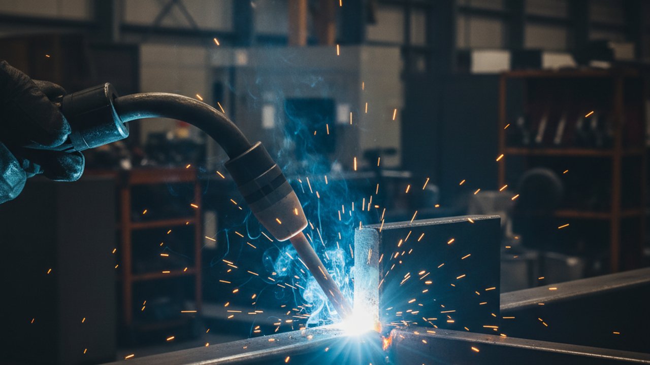
MAG (Metal Active Gas) welding is the GMAW variant run with an active shielding gas — typically CO2 or an argon/CO2 blend — rather than the inert argon a classic MIG setup uses. The hotter, more fluid arc that results is part of why the pool’s visible signature of drift is quick and easy to miss without a direct read.
Arc-parameter monitoring taps the welding circuit and the wire-drive control loop: voltage and current at the torch, wire feed speed, and — on systems built for it, such as WeldTrace — shielding gas flow, sampled fast enough to resolve individual short-circuit or droplet-detachment events. It is an electrical and mechanical record; it never sees the pool, the arc plasma, or a spatter particle, only the current draw and voltage response those things produce.
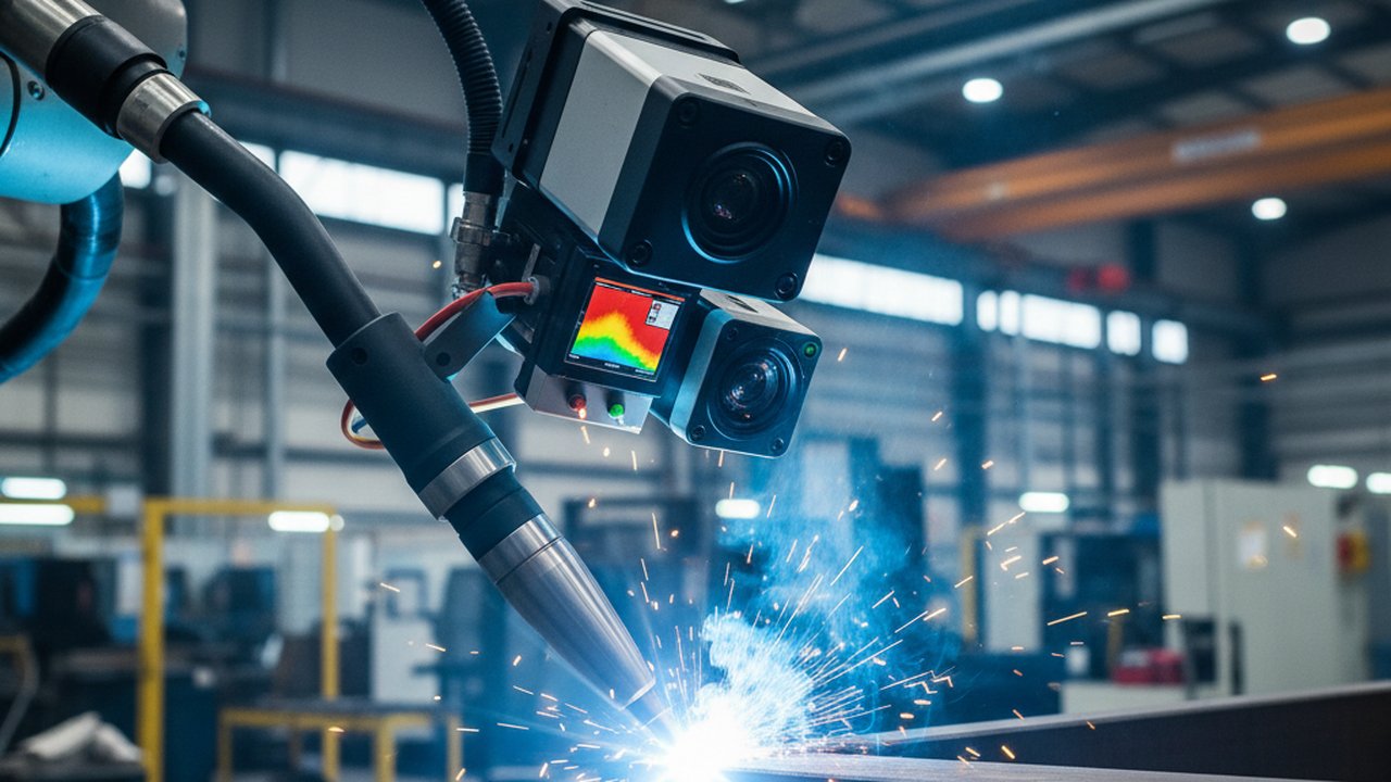
Camera monitoring — visual, thermal, or both — reads the process the way an experienced welder’s eye would, but continuously: pool outline and symmetry, fume plume shape, spatter ejection and landing pattern, and the visible rhythm of metal transfer. It is a direct image, not an inference from an electrical proxy.
Pool shape: a read only a camera provides
Pool shape is the clearest case of a channel arc parameters simply do not carry. A healthy MAG pool holds a symmetric outline centered on the joint; when the torch drifts off the seam or heat input runs ahead of what the joint geometry can absorb, the pool skews or over-widens. On a straight, non-weaving pass with no through-arc seam tracking, none of that has a direct electrical signature — voltage and current can stay within their normal band while the pool visibly moves off-center, because on that kind of pass the electrical circuit carries no reference to where the joint is.
A weld pool camera resolves this as an outline against the joint, not a number against a threshold. The same applies to the pool’s cooling and solidification behavior once the arc has passed — visible on high-speed video well before it could be reconstructed from an arc-parameter log alone.
Transfer regularity: what the electrical signature can and cannot tell you
MAG welding runs one of a handful of metal transfer modes — short-circuit (dip), globular, or spray — depending on current, voltage, wire diameter, and shielding gas composition. This is the one area where arc parameters carry real information about the transfer itself, not just a proxy for it: a high-sample-rate voltage/current capture can count short-circuit events per second and how regular their spacing is, the standard basis for classifying transfer mode electrically.
What that count cannot show is the geometry of each event — droplet size, whether detachment is on-axis or thrown sideways, and whether a given dip runs clean or spatter-generating. A high-speed camera resolves transfer mode directly, frame by frame, which is also how an unstable pattern gets diagnosed rather than just flagged: the same distinction shows up in why droplet transfer becomes unstable on a controlled-transfer process, where the electrical trace and the video tell different parts of the same story.
Gas pores from a shielding lapse are not one single classification — ISO 6520-1 separates uniformly distributed, clustered, and linear porosity into distinct reference numbers within its cavity group, because the distribution pattern points to a different cause in each case. The reference card for the base entry is 2011 — porosity; this article does not restate ISO 5817’s acceptance levels for it — those belong in the standard itself.
Spatter: seen or inferred
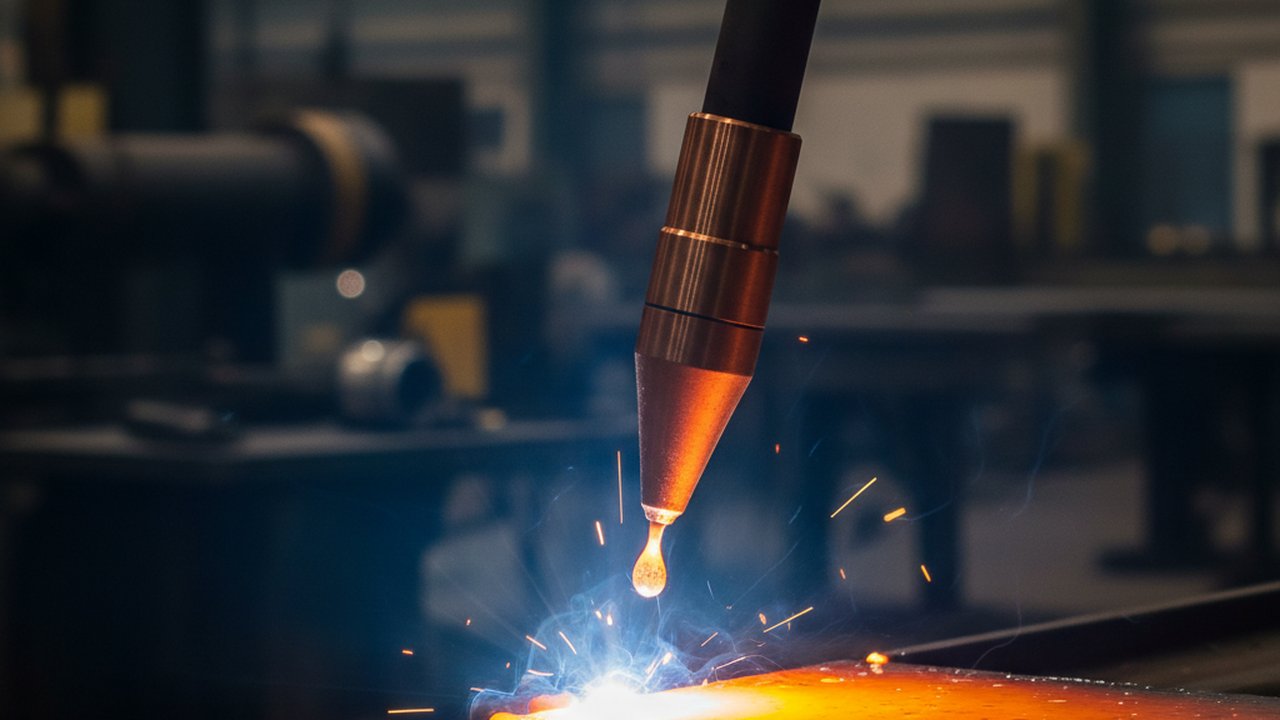
Spatter is where the gap between the two channels is most visible, because it is a physical object landing on and around the joint, not a purely electrical event. A camera counts what is actually ejected and can show a landing pattern shifting before anything else changes — more particles, a wider scatter, spatter reaching areas of the part it normally does not. An arc-parameter system has no equivalent direct read: the closest proxy is a rise in short-circuit dip frequency or a drop in arcing-time ratio, both of which correlate with spatter tendency on average without counting a single actual particle or showing where it goes.
That gap matters for root cause as much as detection. Weld spatter has several distinct causes — excess wire feed speed relative to travel speed, wrong polarity, gas coverage, contact-tip-to-work distance — and an electrical proxy that only says “tendency is up” gives no help isolating which. Watching the transfer directly usually does; the glossary entry for spatter has the short definition.
Which defects each channel catches first
Neither channel is strictly earlier across every failure mode — it depends on where the problem physically starts.
Camera catches first, because the first symptom is optical or geometric:
- A partial gas-coverage lapse changes fume plume shape and arc color before porosity has fully formed, and usually before voltage or current leave their normal noise band — the same logic covered in why fume plume shape signals arc stability.
- Pool skew from torch misalignment or fit-up drift, on a straight pass with no through-arc seam tracking, since the electrical circuit then has no reference to where the seam actually is.
- A spatter landing pattern widening toward the joint, ahead of any electrical proxy crossing a threshold.
Arc parameters catch first, because the first symptom is inside the electrical or mechanical control loop:
- Wire feed speed hunting from a liner drag point or a slipping drive roll — the wire-feed trace shows it directly; a camera only sees the resulting bead-width variation once it has already happened.
- A voltage sag from a loose ground or worn contact tip, visible in the trace before it changes the pool enough to show on video.
- A wire-feed-to-travel-speed mismatch drifting the procedure away from its qualified heat-input range — a calculation from logged parameters, not something a camera frame shows on its own.
When arc parameters alone are enough, and when they are not
If the question is procedure conformance — did this production weld run inside the voltage, current, and wire-feed-speed band the WPS calls for — a continuous arc-parameter log answers it well and cheaply, for every weld without exception. That is the case welding parameter monitoring is built for: proving what the machine delivered, not what the result looked like.
If the question is instead the process result — did the pool stay centered, was transfer clean, did spatter land where it always does — arc parameters alone cannot answer it, because none of those are electrical quantities. That is the case for a welding monitoring system built around cameras and thermal imaging, and why most production cells running MAG at real duty cycle end up with both: the electrical log for conformance, the visual and thermal read for the geometry that only ever shows up as shape or light. Which channel would have caught a specific defect earliest is worth testing on your own line the same way covered for burn-through: a deliberately marginal pass, filmed and logged at once, compared frame by frame against the timestamp — not assumed from a general rule.
FAQ
What is the difference between monitoring MAG welding by camera and by arc parameters? Arc-parameter monitoring reads the electrical circuit — voltage, current, wire feed speed, and sometimes gas flow — and infers what the arc is doing from that signature. A camera reads the process directly: pool geometry, spatter ejection, and metal transfer are seen as images, not inferred from an electrical proxy. Neither channel is a replacement for the other; they answer different questions.
Can arc voltage and current alone tell you the metal transfer mode in MAG welding? Reasonably well, within limits. A high-sample-rate waveform capture can count short-circuit events per second and their regularity, which is the standard way transfer mode is classified electrically. What it cannot show is droplet geometry, off-axis detachment, or where the resulting spatter lands — those need a direct optical read.
Which MAG welding defects does a camera catch before arc parameters would show anything? Anything whose first symptom is shape rather than current draw: a pool skewing off the joint centerline from torch misalignment on a pass without through-arc seam tracking, a gas-coverage lapse changing pool color and fume plume shape before porosity forms, or spatter landing pattern shifting before any voltage or current trend moves outside its normal band.
Which MAG welding problems show up in arc parameters before a camera would catch them? Anything that happens inside the wire-feed and power-source control loop rather than at the pool surface: wire-feed speed hunting from a liner or drive-roll issue, a voltage sag from a loose ground connection, or a wire-feed-to-travel-speed mismatch. These are electrical or mechanical events at the source, and a camera only sees their downstream effect on the bead once it has already changed shape.
Why does gas coverage matter for what each monitoring channel sees first? On a partial shielding-gas coverage lapse, the arc plasma and fume plume shape usually change before the electrical signature is distinguishable from ordinary process noise. A camera or thermal channel watching the plume and pool color typically picks this up earlier than a voltage/current trace, which only responds once porosity has already started forming in the solidifying pool.
Does spatter frequency measured electrically match what actually lands on the part? Not directly. An electrical proxy — short-circuit dip count, arcing-time ratio — correlates with spatter tendency because more disturbed transfer produces more spatter on average, but it counts electrical events, not particles. A camera counts what is actually ejected and can show where it lands relative to the joint, which the electrical signature cannot.
See the pool, not just the current draw
Therness combines high-speed pool imaging with logged arc parameters so a MAG weld is read on both channels at once, not one or the other.
Talk to an engineerTherness solution: Welding camera — Thermal and high-speed imaging that watches the arc, the pool and the cooling seam while the weld is made.
Frequently Asked Questions
What is the difference between monitoring MAG welding by camera and by arc parameters?
Arc-parameter monitoring reads the electrical circuit — voltage, current, wire feed speed, and sometimes gas flow — and infers what the arc is doing from that signature. A camera reads the process directly: pool geometry, spatter ejection, and metal transfer are seen as images, not inferred from an electrical proxy. Neither channel is a replacement for the other; they answer different questions.
Can arc voltage and current alone tell you the metal transfer mode in MAG welding?
Reasonably well, within limits. A high-sample-rate waveform capture can count short-circuit events per second and their regularity, which is the standard way transfer mode is classified electrically. What it cannot show is droplet geometry, off-axis detachment, or where the resulting spatter lands — those need a direct optical read.
Which MAG welding defects does a camera catch before arc parameters would show anything?
Anything whose first symptom is shape rather than current draw: a pool skewing off the joint centerline from torch misalignment on a pass without through-arc seam tracking, a gas-coverage lapse changing pool color and fume plume shape before porosity forms, or spatter landing pattern shifting before any voltage or current trend moves outside its normal band.
Which MAG welding problems show up in arc parameters before a camera would catch them?
Anything that happens inside the wire-feed and power-source control loop rather than at the pool surface: wire-feed speed hunting from a liner or drive-roll issue, a voltage sag from a loose ground connection, or a wire-feed-to-travel-speed mismatch. These are electrical or mechanical events at the source, and a camera only sees their downstream effect on the bead once it has already changed shape.
Why does gas coverage matter for what each monitoring channel sees first?
On a partial shielding-gas coverage lapse, the arc plasma and fume plume shape usually change before the electrical signature is distinguishable from ordinary process noise. A camera or thermal channel watching the plume and pool color typically picks this up earlier than a voltage/current trace, which only responds once porosity has already started forming in the solidifying pool.
Does spatter frequency measured electrically match what actually lands on the part?
Not directly. An electrical proxy — short-circuit dip count, arcing-time ratio — correlates with spatter tendency because more disturbed transfer produces more spatter on average, but it counts electrical events, not particles. A camera counts what is actually ejected and can show where it lands relative to the joint, which the electrical signature cannot.