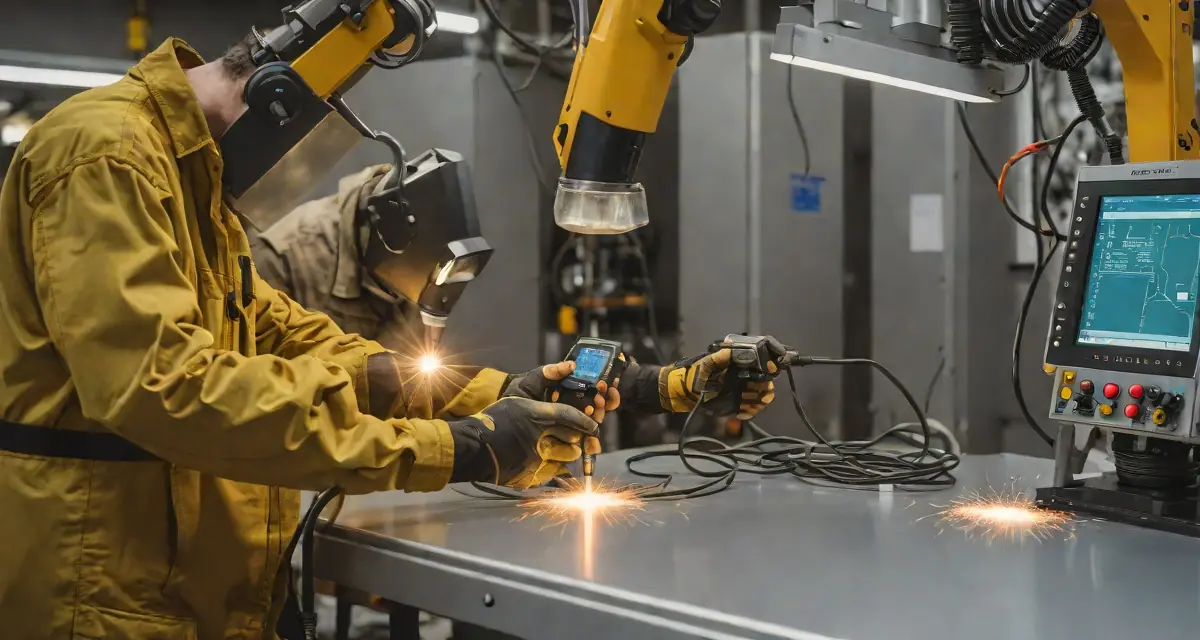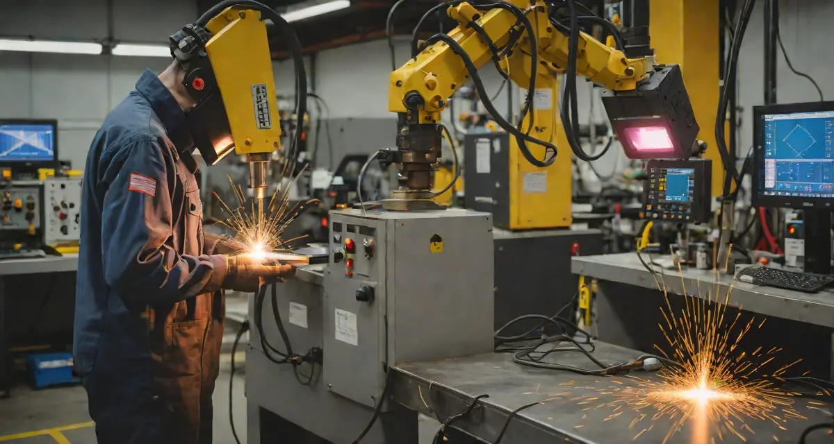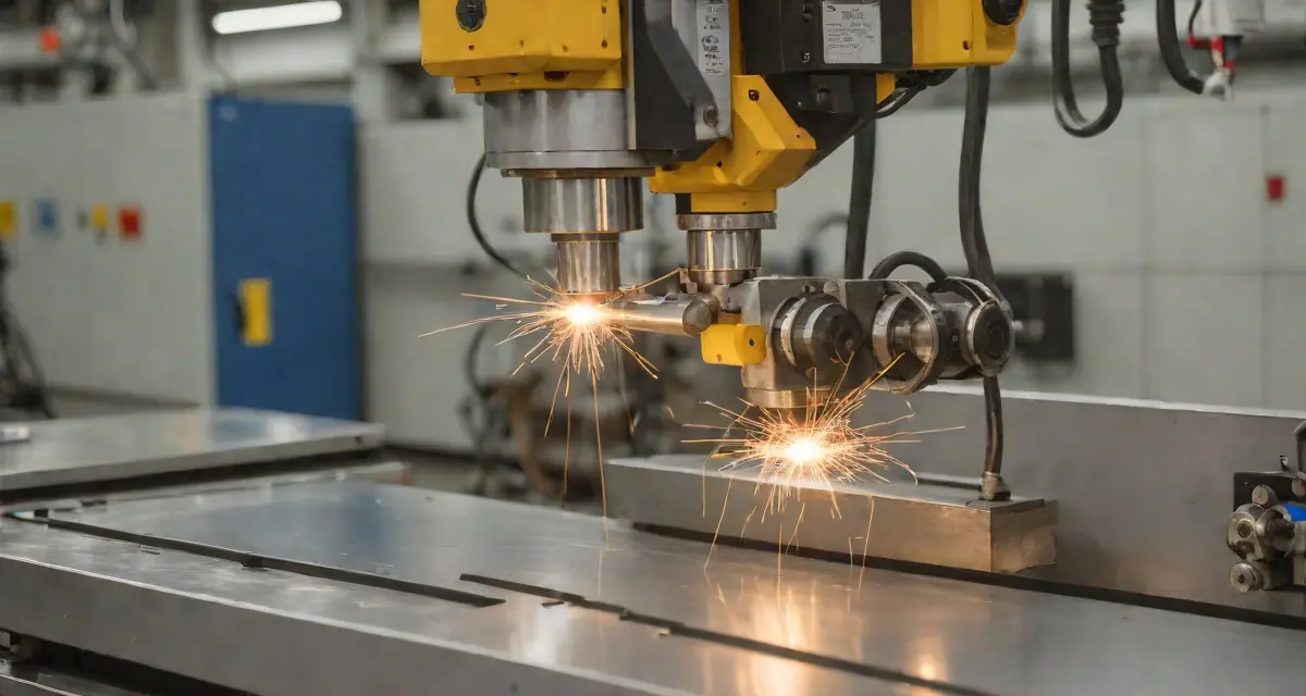
Friction stir welding quality monitoring is rapidly moving from laboratory research to production-floor necessity. As aerospace, EV battery, and shipbuilding manufacturers scale FSW processes to higher volumes and tighter tolerances, the gap between what traditional post-weld inspection catches and what real-time monitoring can prevent has become a critical competitive differentiator.
FSW produces solid-state, low-distortion joints in materials that are notoriously difficult to fusion-weld—aluminium alloys, copper, titanium, and dissimilar-metal combinations. But “solid-state” does not mean defect-free. Voids, kissing bonds, lack of penetration, and hooking defects are FSW’s signature failure modes, and they often escape visual and radiographic inspection until a structural test reveals them under load.
This guide explains how thermal imaging-based friction stir welding quality monitoring detects these defects inline—at production speed—and how leading manufacturers embed a real-time weld monitoring system into their quality workflows.
Why FSW Demands a Different Monitoring Approach
Friction stir welding differs fundamentally from fusion processes like GMAW, MIG, and TIG welding. The FSW tool generates heat through friction and plastic deformation rather than an electric arc or laser beam, creating a plasticised material flow around a rotating pin. This solid-state mechanism delivers exceptional joint properties—low porosity, minimal distortion, no fusion zone—but it also creates failure modes that standard arc-welding monitoring cannot address.
The key challenge: FSW defects are highly parameter-sensitive. A change of 50 RPM in rotational speed, or a plunge depth error of 0.1 mm, can shift a defect-free weld into a void-generating regime without any visible change to the weld surface. The joint looks complete. The surface flash appears normal. Only a cross-section or tensile test reveals the internal void.
Traditional quality control strategies—post-weld radiography, ultrasonic testing, destructive sampling—catch these problems late, after significant value has been added to the workpiece. In aerospace applications, where FSW panels may weigh hundreds of kilograms and carry weeks of machining value, the cost of a rejected joint discovered at final inspection is substantial.
FSW defects like kissing bonds and subsurface tunnels can be invisible on the weld surface and escape standard visual and dye-penetrant inspection. Real-time thermal monitoring during the weld pass is the only reliable method for 100% inline detection.
The Thermal Signature of FSW Defects
Every FSW defect has a thermal signature. This is the physical basis for infrared thermography-based friction stir welding process monitoring.
During a healthy FSW pass, the temperature field behind the tool displays a characteristic asymmetric pattern: the advancing side runs slightly hotter than the retreating side due to the combined effect of rotational and translational velocity. Heat generation is dominated by shoulder friction and plastic dissipation in the thermo-mechanically affected zone (TMAZ). A trained thermal model—or an AI system trained on thousands of passes—learns to recognise what a “normal” temperature distribution looks like for a given alloy, tool geometry, and parameter set. It helps to watch real-time thermal imaging of a live weld pass to see how this trailing heat field is captured frame by frame.
Defect conditions disrupt this signature in detectable ways:
Voids and tunnel defects reduce local thermal mass and interrupt material flow continuity. A void beneath the shoulder contact zone appears as a localised cold anomaly in the trailing heat field—a distinct deviation from the expected gradient.
Kissing bonds and lack of penetration alter heat conduction paths at the weld root. Because the bond line is incomplete, thermal conductivity across the joint is lower than nominal. A calibrated thermal camera mounted on the opposite face of the workpiece can detect the subtle temperature differential caused by this reduced conductivity.
Excessive heat input — caused by too-slow travel speed or too-high rotational speed — produces abnormally wide heat-affected zones and can indicate tool wear or plunge depth drift. The preheat and interpass temperature monitoring principles that govern arc welding apply equally here: temperature uniformity is a proxy for process control.
Tool wear changes the friction coefficient progressively, increasing the energy required to maintain a given temperature. A slow upward drift in the trailing temperature field—while rotational speed and feed remain constant—is a leading indicator of tool degradation before it produces rejects.
| Defect | Thermal Indicator | Detection Zone |
|---|---|---|
| Void / tunnel | Cold anomaly in trailing field | Retreating side, mid-thickness |
| Kissing bond | Reduced conductivity at root | Opposite face |
| Excess heat input | Wide HAZ, elevated peak T | Both sides |
| Tool wear | Gradual T-drift at constant params | Advancing side |
| Lack of penetration | Root temperature deficit | Back face monitoring |
Sensor Configuration for In-Process FSW Monitoring
Implementing friction stir welding process monitoring with thermal imaging requires attention to sensor placement and spectral selection that differs from arc-welding applications.
Spectral band: FSW operates at temperatures well below fusion welding—typically 400–550°C for aluminium alloys. Mid-wave infrared (MWIR, 3–5 µm) cameras offer superior sensitivity in this range compared to shortwave (SWIR) systems calibrated for arc temperatures above 1400°C. For steel and titanium FSW, which operate at higher temperatures, the optimal band shifts accordingly.
Camera placement options:
- Trailing thermal field camera — mounted at a fixed offset behind the tool shoulder, this is the most common configuration. It captures the heat-affected zone as it solidifies, providing a continuous record of the thermal history across the full weld length.
- Opposing face camera — for lap joints and applications where root defect sensitivity is critical, a second camera on the back face monitors conduction-through-thickness to detect lack-of-penetration signatures.
- In-spindle or near-spindle monitoring — some advanced implementations embed a thermal sensor within the tool assembly to monitor spindle torque and temperature simultaneously, providing a tighter correlation between process state and defect risk.
Frame rate and resolution: FSW travel speeds typically range from 100–500 mm/min for aluminium alloys, which is slower than laser welding but requires sustained monitoring over longer weld lengths. A frame rate of 50–100 Hz at 640×512 pixel resolution is sufficient for most FSW configurations. Higher frame rates are needed only for friction stir spot welding (FSSW), where the dwell cycle is short.
Unlike laser welding monitoring, which requires microsecond-level temporal resolution to capture keyhole dynamics, FSW thermal monitoring can use standard industrial MWIR cameras operating at 50–100 Hz. This significantly reduces sensor cost while maintaining detection capability.
Aluminium FSW in EV Battery Manufacturing: A High-Stakes Application
The growth of electric vehicle production has driven FSW adoption into one of its most demanding applications: sealing aluminium battery enclosures. FSW is preferred over MIG or laser welding for battery tray lids because it produces leak-tight, low-distortion joints in 5xxx and 6xxx series alloys without the porosity risk associated with fusion processes.
But the quality stakes are severe. A kissing bond or micro-void in a battery enclosure weld can compromise the IP67/IP69K sealing integrity required for thermal management systems. Field failures in automotive battery packs carry product liability consequences that extend far beyond the cost of the weld itself—as covered in reducing automotive liability through quality control.
For EV battery enclosure FSW, best-practice monitoring integrates:
- Continuous trailing-field thermal imaging for 100% inline coverage of every weld centimetre
- Plunge depth telemetry correlated with thermal data to detect shoulder lift-off
- Rotational speed and torque logging to identify tool wear trends before they produce rejects
- Statistical process control (SPC) on thermal parameters — the same SPC methodology applied to arc welding translates directly to FSW with appropriate control limits
The output is a per-weld thermal record that serves as objective evidence of conformance — analogous to the welding data historian and MES integration approach used in arc-welding production cells.
Aerospace FSW: Certification and Traceability Requirements
Aerospace applications of FSW — including fuselage panels, wing skins, fuel tanks, and rocket pressure vessels — operate under the most stringent traceability and qualification frameworks in manufacturing. The ISO 15614 weld procedure qualification framework does not yet include a dedicated FSW annex, but aerospace customers typically require:
- A qualified weld procedure specification (WPS) validated by destructive tests on representative material
- Per-unit process records showing that all monitored parameters remained within qualified envelopes
- Evidence that no thermal anomaly indicative of a defect was detected during production
Thermal imaging monitoring satisfies the third requirement natively. A system that records every frame of every weld pass, tags anomalies against position data, and stores the record in a searchable archive provides the kind of objective conformance evidence that NDT alone cannot deliver.
For aerospace manufacturers working under ISO 3834 quality requirements, the process monitoring record is a first-party quality record. When combined with periodic destructive validation samples, it supports the argument for reduced end-item NDT frequency — a direct operating cost benefit that justifies the sensor investment.
Aerospace FSW operators using continuous thermal monitoring have reported reductions in post-weld NDT inspection time of 30–50%, by substituting inline process records for a portion of volumetric (UT/RT) inspections on production conformance joints.
Shipbuilding and Marine FSW Applications
Shipbuilders have adopted FSW for aluminium superstructures, deck panels, and hull sections. The ISO 3834-2:2021 framework for fusion welding quality requirements is increasingly referenced for solid-state processes by shipbuilding classification societies, which require documented evidence of process control.
Marine FSW introduces additional monitoring complexity: long weld lengths (often exceeding 10 metres), panel distortion from clamping variability, and environmental temperature fluctuations that affect baseline thermal readings. Effective FSW quality monitoring systems for marine applications compensate for ambient temperature drift using reference emitters, and correlate weld-start thermal transients against steady-state baselines to avoid false alarms during ramp-up.
The weld distortion monitoring techniques used in fusion welding — particularly for large panel structures — complement FSW thermal monitoring by capturing out-of-plane deflection in real time, enabling clamping force adjustments before they affect weld quality.
Integration with Digital Quality Systems
A thermal monitoring dataset without a digital record is an inspection event without a certificate. The value of friction stir welding quality monitoring compounds when the data is integrated into a quality management system that links process records to:
- Individual joint identity (weld ID, serial number, drawing reference)
- Tool identity and wear history
- Material batch and heat treatment records
- Post-weld NDT results
This is the data model that digital welding quality records support — and it applies as directly to FSW as to arc welding. The AWS D17.3/D17.3M standard for fusion welding of aluminium in aerospace, and the broader ISO 25239 series for friction stir welding, both converge on the requirement for documented process control.
For manufacturers implementing welding QMS software across multiple welding processes, FSW thermal monitoring data should feed the same database as arc-welding process records — enabling cross-process quality analytics and unified audit trails.
Before deploying FSW thermal monitoring, confirm your quality system supports:
- Weld-ID-to-thermal-record linkage (one-to-one, not batch)
- Automatic anomaly flagging with position coordinates
- Parameter envelope breach logging (RPM, feed, plunge depth)
- Thermal record export in open format (CSV, HDF5, or DICOM-IR)
- NDT result correlation for closed-loop validation sampling
ROI Model for FSW Thermal Monitoring
The business case for friction stir welding process monitoring follows the same structure as any inline quality investment: the return comes from avoided rework, scrap, and field failures, not from the monitoring system itself.
For a representative aerospace FSW application — aluminium wing rib panels, 50 units per week, average panel value $4,000 — consider:
- Baseline reject rate without monitoring: 2–3% detected at post-weld UT, plus an estimated 0.5% escaping to assembly
- Rework cost per reject: $800–$1,200 (re-clamp, re-weld, re-inspect)
- Escape cost per field escape: $15,000+ (assembly tear-down, liability exposure)
- Monitoring system annualised cost: $35,000–$60,000 (sensor + software + integration)
At 50 units/week, a 2% reject rate generates ~52 rejects/year. Reducing this by 60% through early defect detection (catching parameter drift before it produces full voids) saves approximately 31 rework events/year at $1,000 average — $31,000 — plus eliminating 2–3 assembly escapes at $15,000 each: $30,000–$45,000. Total avoided cost: $61,000–$76,000/year against a $35,000–$60,000 system cost. Payback within 12 months.
This weld defect cost model scales favourably with joint value. For titanium FSW in aerospace or nuclear applications, where workpiece values exceed $10,000 per joint, the ROI case is essentially immediate.
Practical Implementation Path
For manufacturers new to FSW thermal monitoring, a phased implementation reduces deployment risk:
Phase 1 — Baseline characterisation (weeks 1–4): Mount a single MWIR camera in the trailing position. Compare sensors in the Therness thermal monitoring range to match a camera and software tier to your cell. Record thermal data passively for 200–500 weld passes across the production parameter range. Do not yet use the data for go/no-go decisions. Build a baseline thermal envelope database.
Phase 2 — Anomaly detection (weeks 5–12): Enable automated anomaly flagging against the baseline envelope. Correlate flagged events with NDT results on the same joints. Refine the detection threshold to minimise false positives while maintaining sensitivity for known defect types.
Phase 3 — Process control integration (weeks 13+): Feed thermal anomaly signals upstream to the motion controller. Implement automatic feed-rate reduction when temperature drift exceeds a defined threshold. Log all parameter adjustments as quality events.
Phase 4 — Audit and certification (ongoing): Export thermal records as part of the first-article inspection (FAI) package. Present to customer quality auditors as process monitoring evidence. Use welding inspection comparison frameworks to document how inline thermal monitoring supplements — or in some cases replaces — a portion of traditional NDT.
Conclusion: FSW Quality Monitoring is No Longer Optional
Friction stir welding has graduated from niche aerospace application to mainstream manufacturing process in EV, marine, and industrial sectors. With that graduation comes the quality assurance burden that customers and certification bodies impose on any mature production process.
Thermal imaging-based FSW quality monitoring meets that burden with a technology that is now proven in production environments, cost-effective relative to the value of FSW joints, and integrable with the digital quality systems that modern manufacturers already operate.
The question is not whether to monitor FSW processes — it is how quickly to move from post-weld inspection to inline detection, and how to integrate the resulting data into a quality architecture that reduces audit burden while improving customer confidence.
Monitor Every FSW Pass — Not Just Random Samples
HeatCore integrates with your FSW production cell to deliver 100% inline thermal monitoring, per-joint traceability, and automatic anomaly detection. Book a technical demo with our applications team.
Book a DemoTherness solution: Welding camera — Thermal and high-speed imaging that watches the arc, the pool and the cooling seam while the weld is made.